This is a continuation of the maintenance record “Replace to LED turn signals 2 【Assemble and install front turn signals】”.
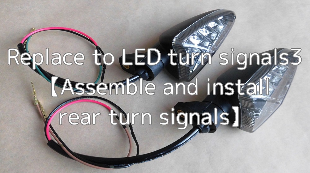
In this third installment, I will assemble and install the rear turn signals.
Since I prepared a similar after-market product (LED turn signal lighting blinker by SAVAGE) for the rear as for the front, wiring modification is required.
Regarding the length of the wiring, the front is the same as the genuine parts, but the rear will match the teil tidy (R&G LP0162BK).
From this article, you can know the following
- How to modify wiring to fit tail tidy
- How to modify the wiring
- Lightweight mounting bolts
| Date | 15th January 2022 |
| Subjects | Tuning, Customizing |
| Shop or DIY | DIY |
| Difficulty | |
| Working hours | 3 |
| Costs [Yen] | 2,724 |
1. Goods to use
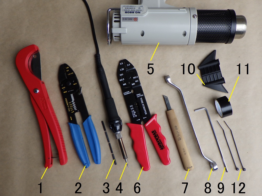
| No. | Products name | Manufacturer | Products number | Quantity | Amounts[Yen] | Purchase this time |
| ST1 | LED turn signals (Length 21mm) | SAVAGE | – | 1 | 2,452 | ○ |
| 1 | Hose cutter | Straight | 19-269 | 1 | 1,680 | |
| 2 | Crimping tool | HOZAN | P-704 | 1 | 4,895 | |
| ST6 | Wire (1m, black) | Sumitomo wiring | AVSSB0.5f | 1 | 132 | |
| ST6 | Wire (1m, green) | Sumitomo wiring | AVSSB0.5f | 1 | 132 | |
| ST6 | Wire (1m, blown) | Sumitomo wiring | AVSSB0.5f | 1 | 132 | |
| 3 | Shrink tube (φ2) | – | – | 1 | 73 | |
| 4 | Soldering iron | TAIYO ELECTRIC | PX-601AS | 1 | 17,600 | |
| 5 | Heating gun | HAKKO | 880B | 1 | (7,260) | |
| ST10 | Type 110 male terminal non-waterproof | Sumitomo wiring | M110 | 4 | 88 | ○ |
| 6 | Crimping tool | Straight | 12-679 | 1 | 630 | |
| 7 | Chisel | – | – | 1 | 1,428 | |
| ST14 | Low head bolts (M6, 16mm, 2 pieces) | YAHATANEJI | 640 | 1 | 184 | ○ |
| 8 | Box wrench (10×12mm) | KTC | M5-1012 | 1 | 1,936 | |
| 9 | Long hex key (3mm) | KTC | HLD150-3 | 1 | 550 | |
| 10 | Wiring insertion tool | Straight | 35-1900 | 1 | 240 | |
| 11 | Insulating tape | OHM | DE1910K | 1 | (84) | |
| 12 | Cable tie (2.5mm) | ELPA | KBF-N100100(BK) | 2 | 175 | |
| 39,671 | 2,724 |
2. Assemble and install rear turn signals (STEP1-26)
Remove rear turn signals
First, remove the rear turn signals from the moto body.
(For details, please refer to the maintenance record “How to remove and install rear turn signals”.)
Wiring processing procedure
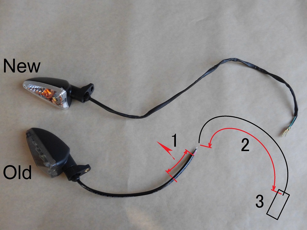
<Wiring processing procedure>
As with the front, the wiring for the LED turn signals is short, so it will be added.
However, for the harness tube, cut the part that overlaps with the corrugated tube to be added later.
The wiring modification proceeds as follows.
- Shorten the length of the harness tube
- Add the wiring
- Install the connector removed in STEP 5 of the maintenance record “How to remove and install rear turn signals.
Remove harness tube
Now, I will begin to modify the wiring for the LED turn signals.
If not noted below, the photo is on the right.
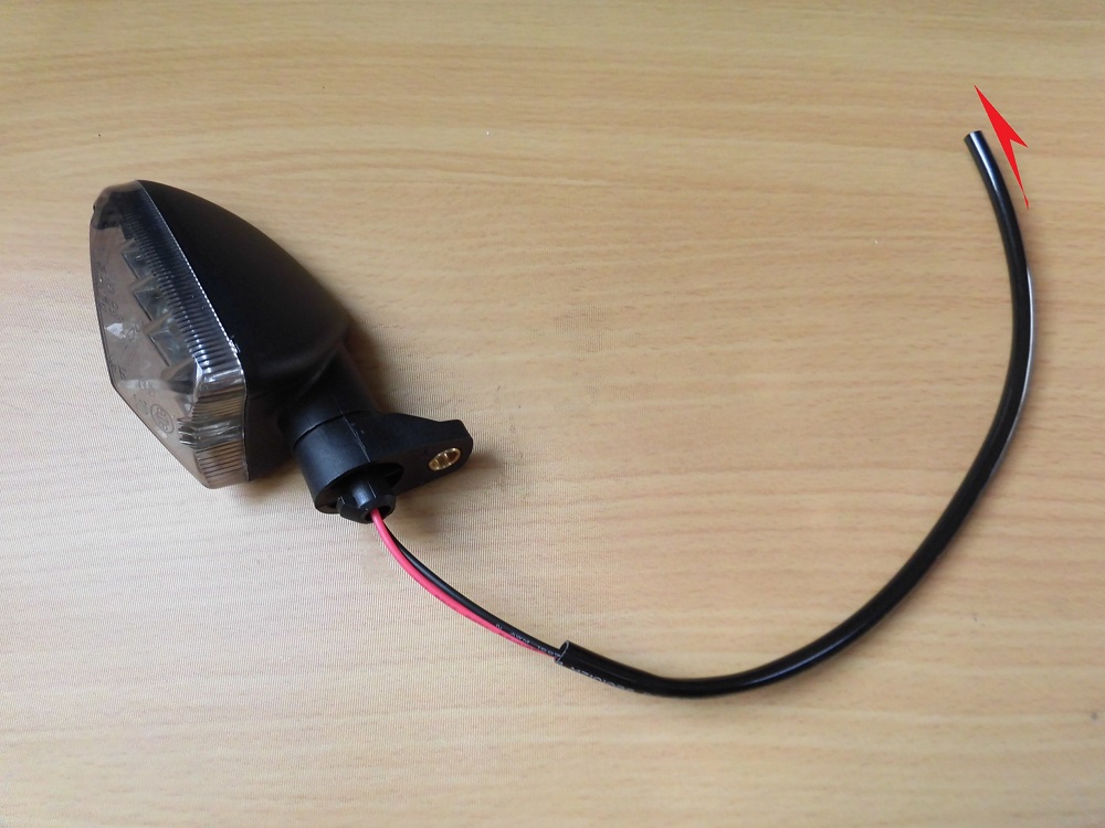
<Remove harness tube>
To cut the harness tube, remove it from the LED turn signals.
If you pull it, it will come off easily.
Unlike the front, this one is not bent violently because the tube was not folded.
Cut harness tube
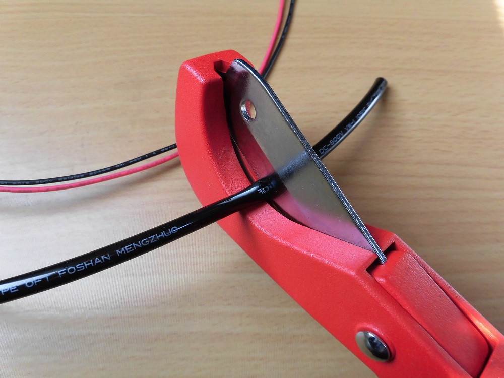
<Cut harness tube>
Using a hose cutter, cut the tube to a length of 140 mm and run it through the wiring.
Protect the wiring with the tube from the turn signal mounting area to the corrugated tube area.
Wiring process 1
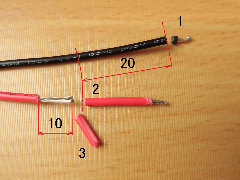
<Wiring process 1>
- Cut the tip of the wiring
- Cut about 20mm off the red wire so that the wiring does not overlap.
- Peel off about 10 mm of the outer covering.
Wiring process 2
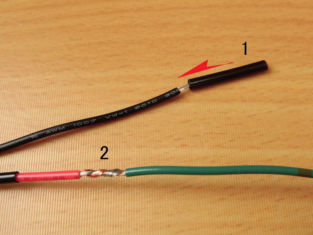
<Wiring process 2>
- Pass the shrink tube through it.
- Pull the LED turn signal wire together with the wire to be added.
Soldering
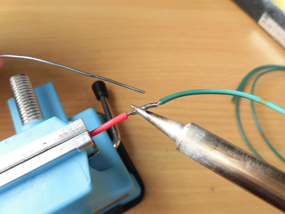
<Soldering>
Apply solder to the distended portion.
Be careful not to apply too much solder to make it easier to pass through the shrink tube.
Flatten the protruding part with nippers.
Heat shrinkage
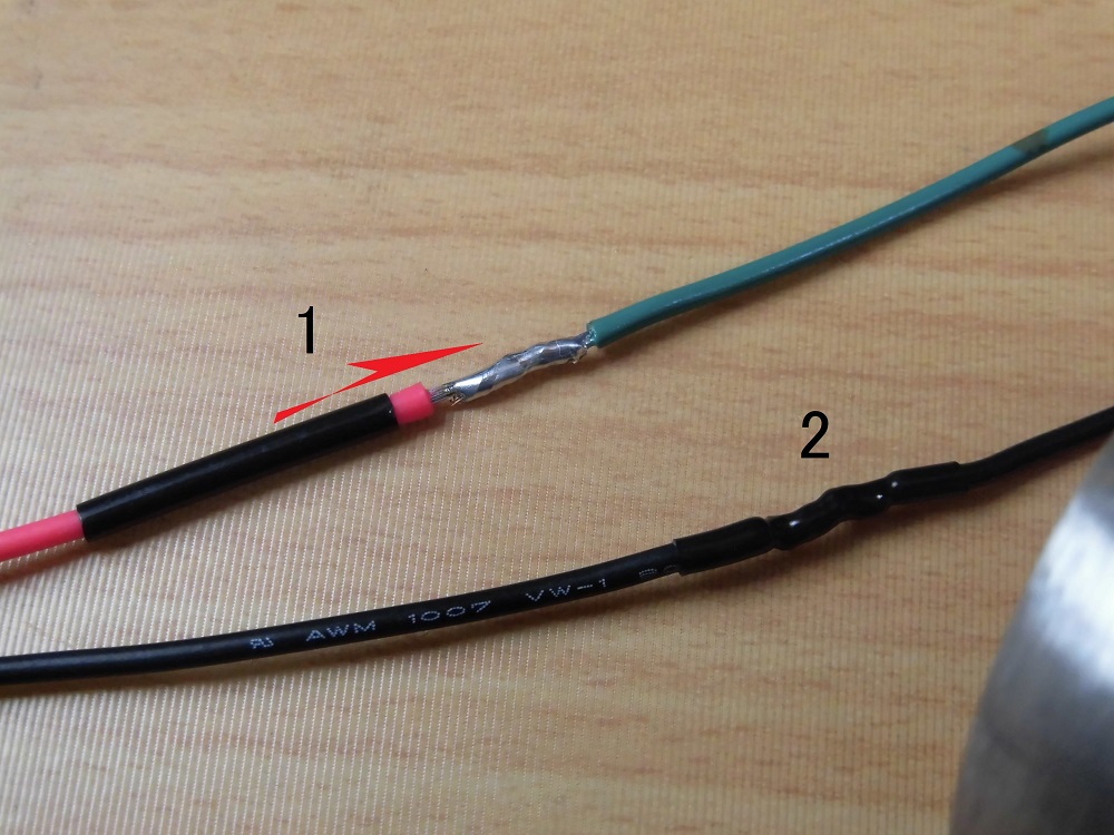
<Heat shrinkage>
- Cover the soldered area with shrink tube.
- Shrink the heat shrink tube with a heat gun.
Wiring process 3
<Wiring process 3>
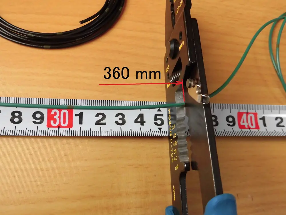
Considering the 70 mm measured in the maintenance record “Wiring for the license plate light” to be posted later, cut the wiring for the LED turn signals at the 360 mm position.
Crimp terminal
Next, crimp the terminals to the wires.
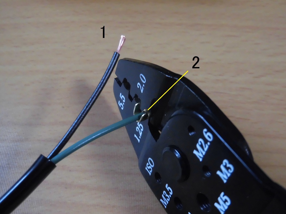
<Crimp terminal>
- Using crimping tool, peel off about 5mm of the outer covering.
- Crimp the terminals with crimping tool.
Modified LED turn signals
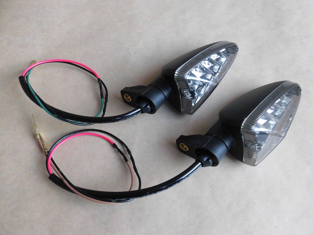
<Modified LED turn signals>
I have not yet attached the LED turn signal connector, but it is indeed shorter.
By the way, it is 6g lighter per side, 12g in total.
I shortened the harness tube, but it was not as light as I expected.
Turn signal mounting area
Now, I will start to install the LED turn signals.
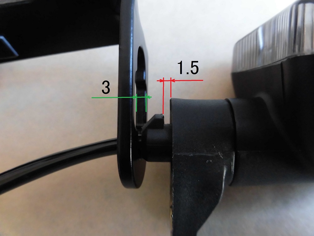
<Turn signal mounting area>
However, the groove of the LED turn signals is too narrow to install on the tail tidy.
After checking, I found that the gap was only about 1.5 mm, compared to the thickness of the tail tidy (gap for genuine parts): 3 mm.
Grooving of turn signals
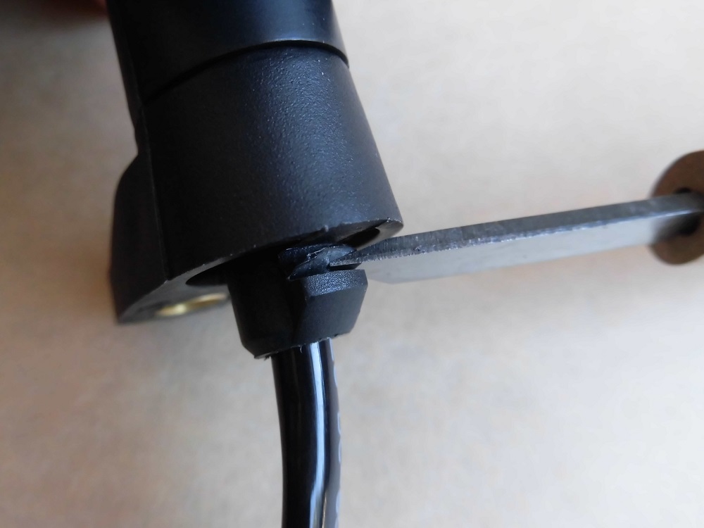
<Grooving of turn signals>
So, I used a chisel to cut the gap until it was about 3mm.
Actually, I did the same for the front.
Install turn signals 1
This time, replace the cap bolts with low head bolts as in the front.
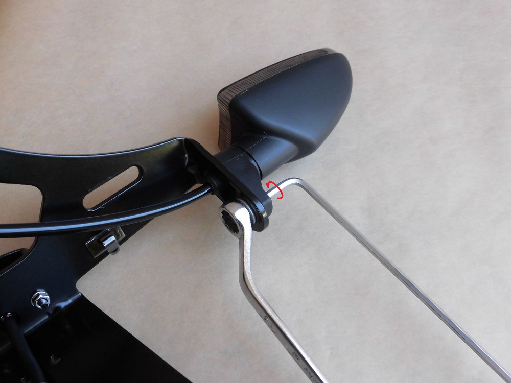
<Install turn signals 1>
Run the wires through the holes in the bracket, then secure with low-head bolts and flange nuts.
Secure the flange nut with a 10 mm box wrench and tighten with a 3 mm long hex key.
Install turn signals 2
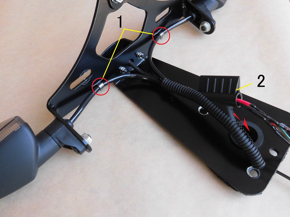
<Install turn signals 2>
- Secure the wires to the bracket with the wiring clamps.
Install the left turn signal blinker in the same way.
- Use the wiring insertion tool to pass the wires through the 120mm corrugated tube.
The corrugated tube will be reused.
There is a little more room for less harness tubes (2 tubes).
Fixed with insulation tape
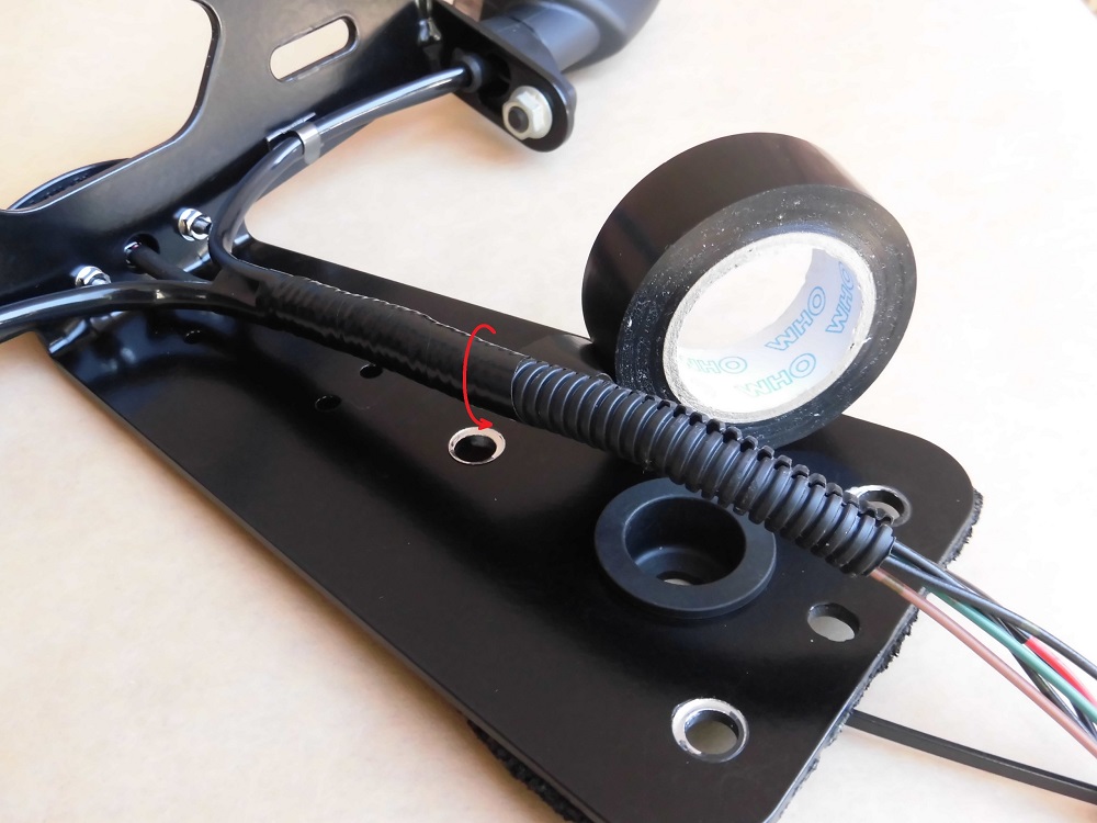
<Fixed with insulation tape>
Insulating tape was wrapped around the entire corrugated tube from the base of the wiring, overlapping each half.
Run through wire
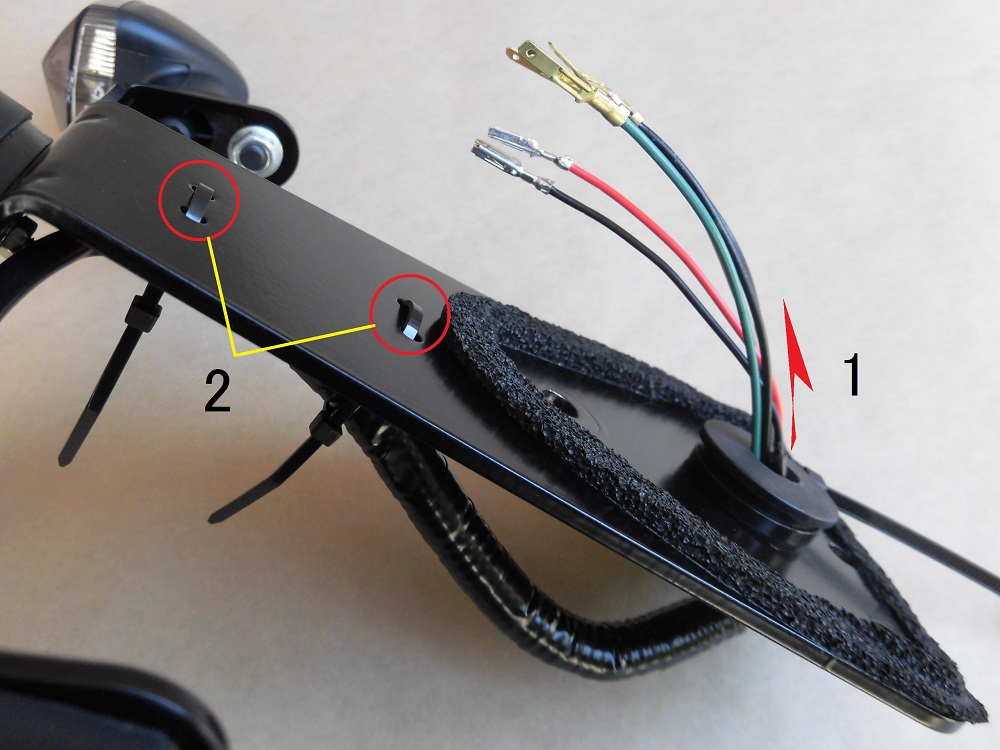
<Run through wire>
- Pass the wiring and corrugated tube through the grommet.
- Temporarily tighten the two ties that secure the corrugated tube.
Since the corrugated tube overlaps with the position of the bolt that installs the bracket to the moto body, tighten the bolt after the bracket is installed on the moto body.
Install connectors
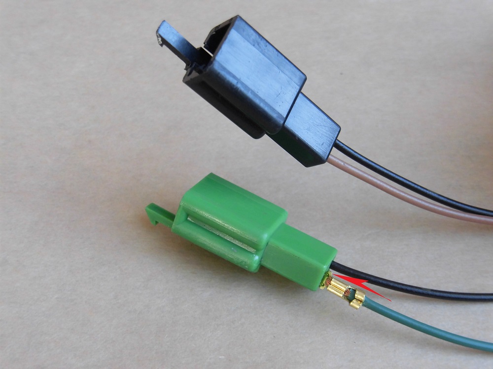
<Install connectors>
Insert the terminals into the connector, paying attention to position and orientation.
Wiring Fixing
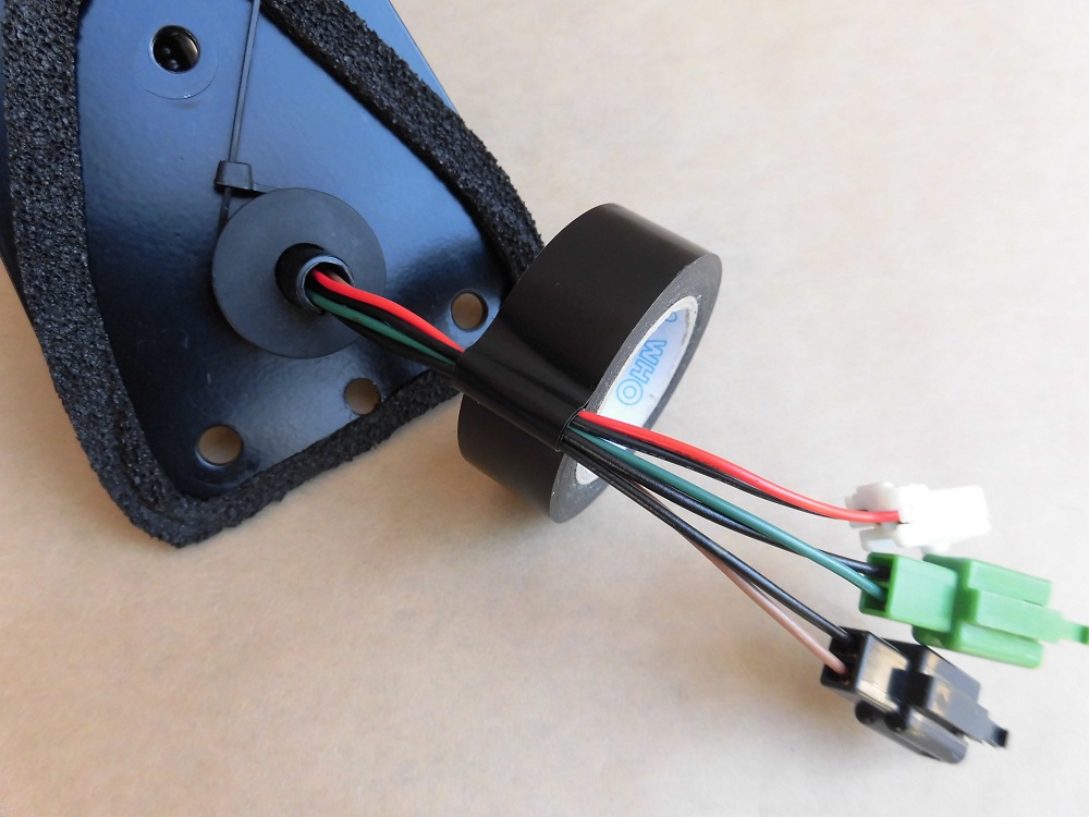
<Wiring Fixing>
To prevent the three wires from coming apart, I put them together with insulation tape.
Assembled tail tidy
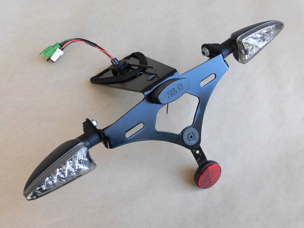
<Front side>
It doesn’t look any different from the last time.
But the wiring length has been shortened.
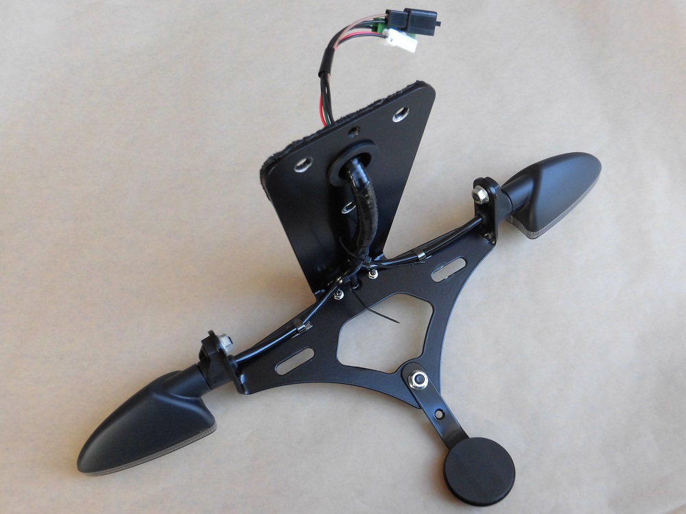
<Reverse side>
Install tail tidy
Then, install the tail tidy to the moto body.
(For details, please refer to the maintenance record “Replace tail tidy4 【Installation】”.
Connect connectors
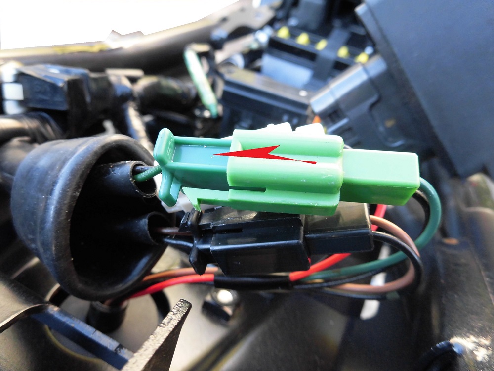
<Connect connectors>
Connect the connector to the wiring on the body side.
Wiring condition
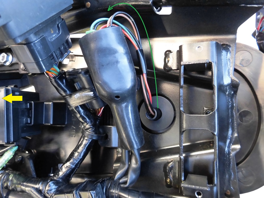
<Wiring condition>
This time, the wiring was routed in this way.
There is no excess wiring and no waste.
Install rear cowls and panel
The rear cowl, panels, etc. are then installed to complete the process.
(For details, please refer to the maintenance record “How to install rear cowls and panel etc.”)
Comparison before and after replacement of mounting bolts
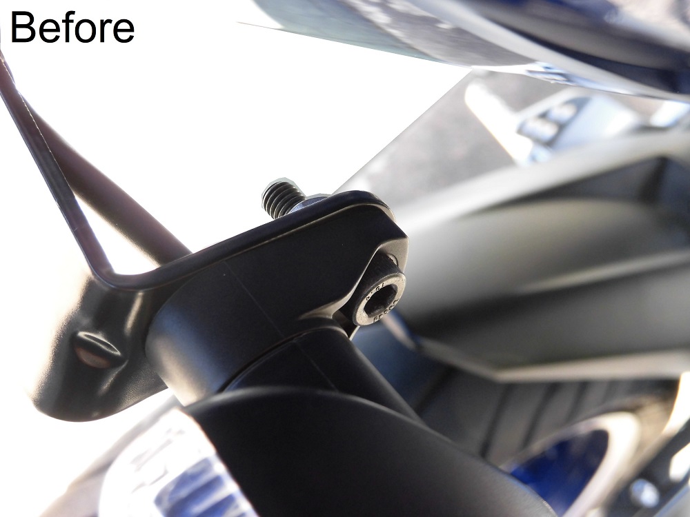
<Before>
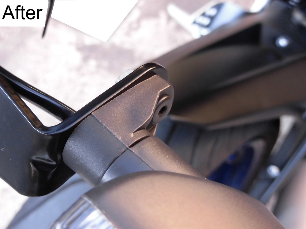
<After>
In fact, I also shortened the length of the screw by 4 mm.
So, the bolt does not protrude from the tip of the flange nut, and it looks good.
Comparison before and after turn signals replacement
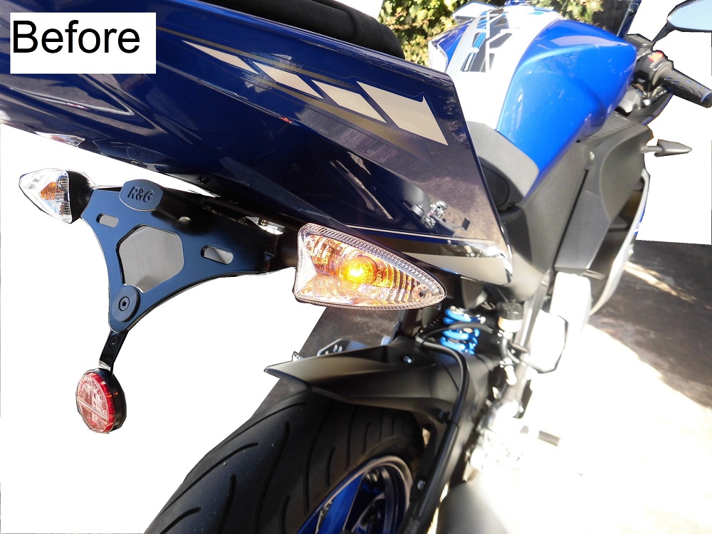
<Before>
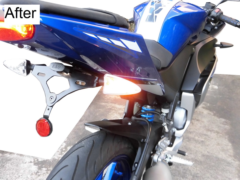
<After>
The shape is the same, so it may not be interesting.
3. Summary
This is a summary of the assembly and installation of the LED rear turn signals.
Along with the replacement with LED turn signals, the wiring length has been matched to the tail tidy. So, the wiring routing has been made easier to handle.
In addition, since I did not use bullet terminals and matched the color of the wiring to the genuine parts, the wiring can be removed and installed in the same way as the genuine parts.
- I was able to put on commercially available LED turn signals with no problem.
- The length of the wiring is recommended to match the tail tidy.
- It is recommended to match the color of the wiring with the genuine parts.
- It is recommended to use 110 type male terminals and crimp the terminals instead of using bullet terminals.
- It is also fun to change the color and shape of the mounting bolts!
