Since the rear turn signals have been replaced with LEDs, this is an opportunity to review the wiring for the license plate lights with regard to the following.
- Make the wiring the proper length to fit the tail tidy.
- Use the connector of the genuine part instead of using bullet connectors or general-purpose connectors.
Note that many parts of this article overlap with the maintenance record “Replace to LED turn signals3【Assemble and install rear turn signals】”. So, I will focus on the wiring and installation of the license plate light.
From this article, you can learn the following.
- License plate light for connectors and terminals
- How to disconnect the terminals from the connector
- How to install the wiring to fit the tail tidy
| Date | 22nd January 2022 |
| Subjects | Tuning, Customizing |
| Shop or DIY | DIY |
| Difficulty | |
| Working hours | 1 |
| Costs [Yen] | 132 |
1. Goods to use
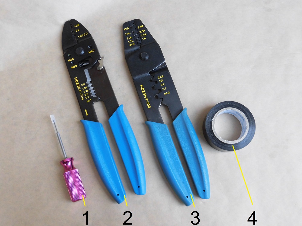
| No. | Products name | Manufacturer | Products number | Quantity | Amounts[Yen] | Purchase this time |
| 1 | Terminal release tool | Straight | 19-1863 | 1 | 1,280 | |
| 2 | Crimping tool | HOZAN | P-704 | 1 | 4,895 | |
| ST9 | 070 series female terminals manufactured by former AMP | TE Connectivity | – | 2 | 132 | ○ |
| 3 | Crimping tool for open barrel contact | HOZAN | P-706 | 1 | 6,743 | |
| 4 | Insulating tape | OHM | DE1910K | 1 | (84) | |
| 13,134 | 132 |
2. Wiring modification of license plate light (STEP1-17)
Remove rear cowls and panel etc.
First, remove the rear cowls and panel, etc.
(For details, please refer to the maintenance record “How to remove rear cowls and panel etc.”)
Check wiring position
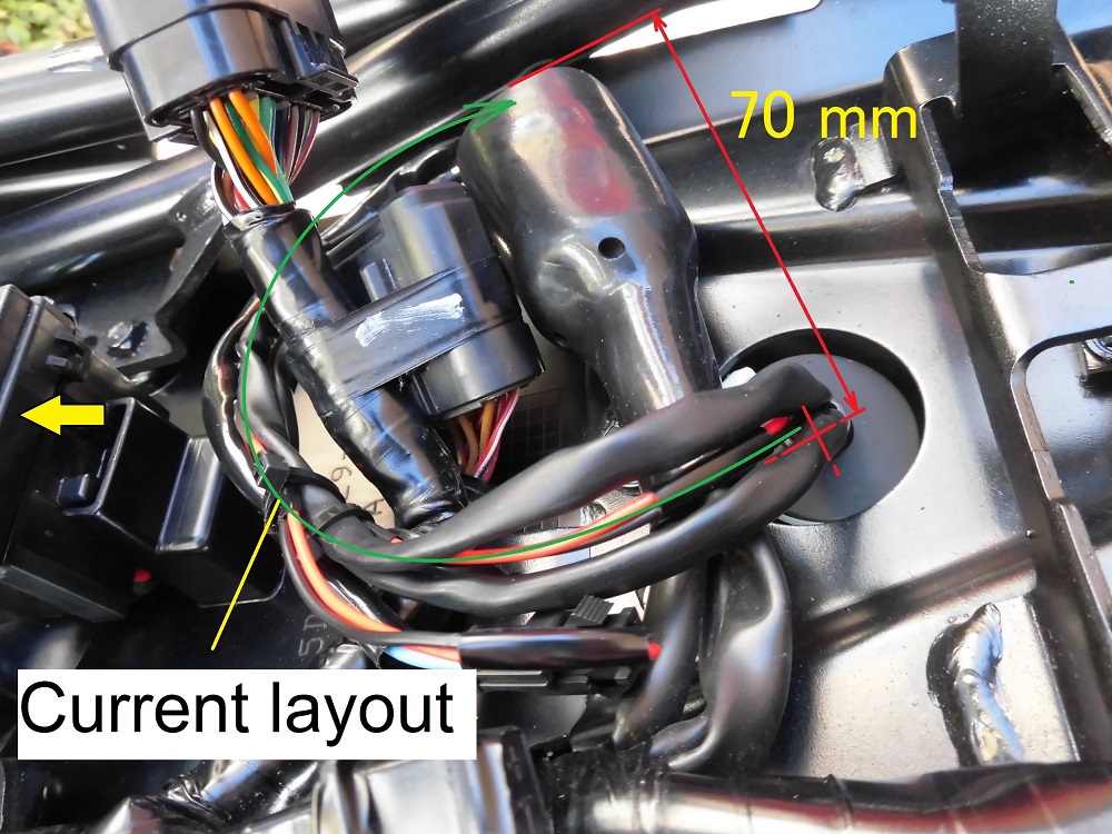
Before disconnecting the wires, check the length of the wires from the tail tidy’s wire outlet to the connectors.
<Check wiring position>
There was approximately 70 mm in a straight line from the tip of the corrugated tube to the connector location.
Use this length as a guide when processing the wiring.
Remove connector
<Remove connector>
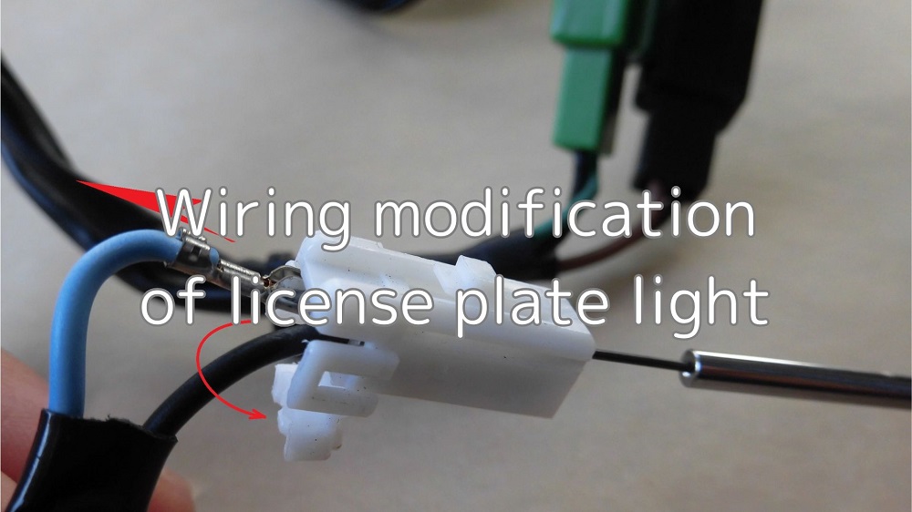
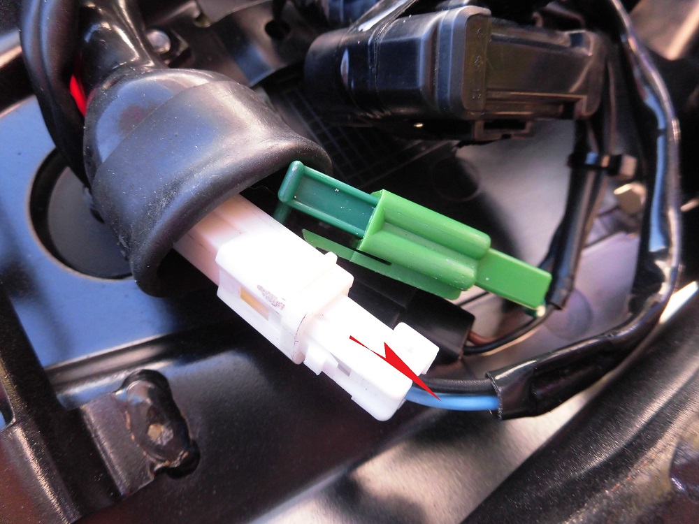
Disconnect the license plate light’s 2-pole white connector from the moto’s wiring.
Push down on the claw part to remove the connector.
Remove terminals
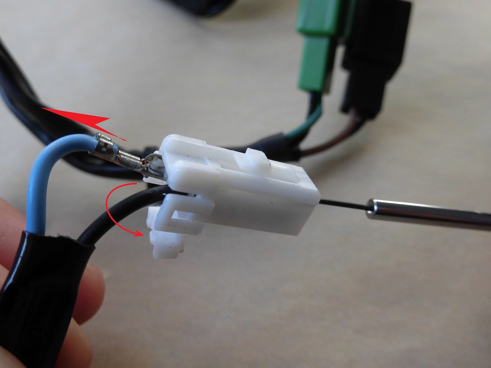
<Remove terminals>
After unlocking the connector, use the terminal release tool to remove the terminals.
Image of terminal removal
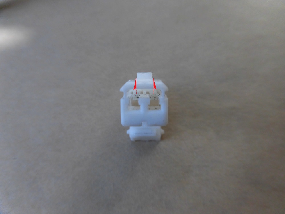
<Image of terminal removal>
The terminal is a female of the 070 series made by former AMP.
The terminal is opened by lifting the protrusion on the arrowhead part.
Remove tail tidy
Next, remove the tail tidy.
(For details, please refer to the maintenance record “How to remove and install rear turn signals” STEP 1-8.)
Wiring processing 1
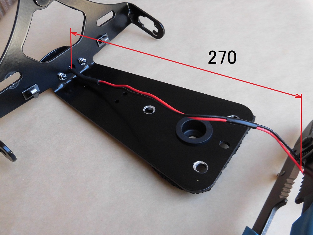
<Wiring processing 1>
Using the 70 mm measured in STEP 2 as a guide, cut the wiring for the license plate light at the 270 mm position.
※The length of this part may vary depending on the tail tidy used.
Cut wiring
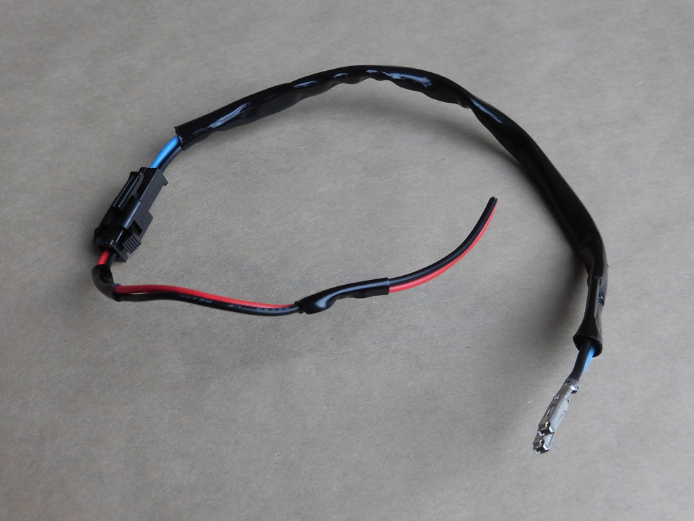
<Cut wiring>
This is the part that was folded and bundled at the moto body side.
The weight is reduced by 8g.
Crimp terminals
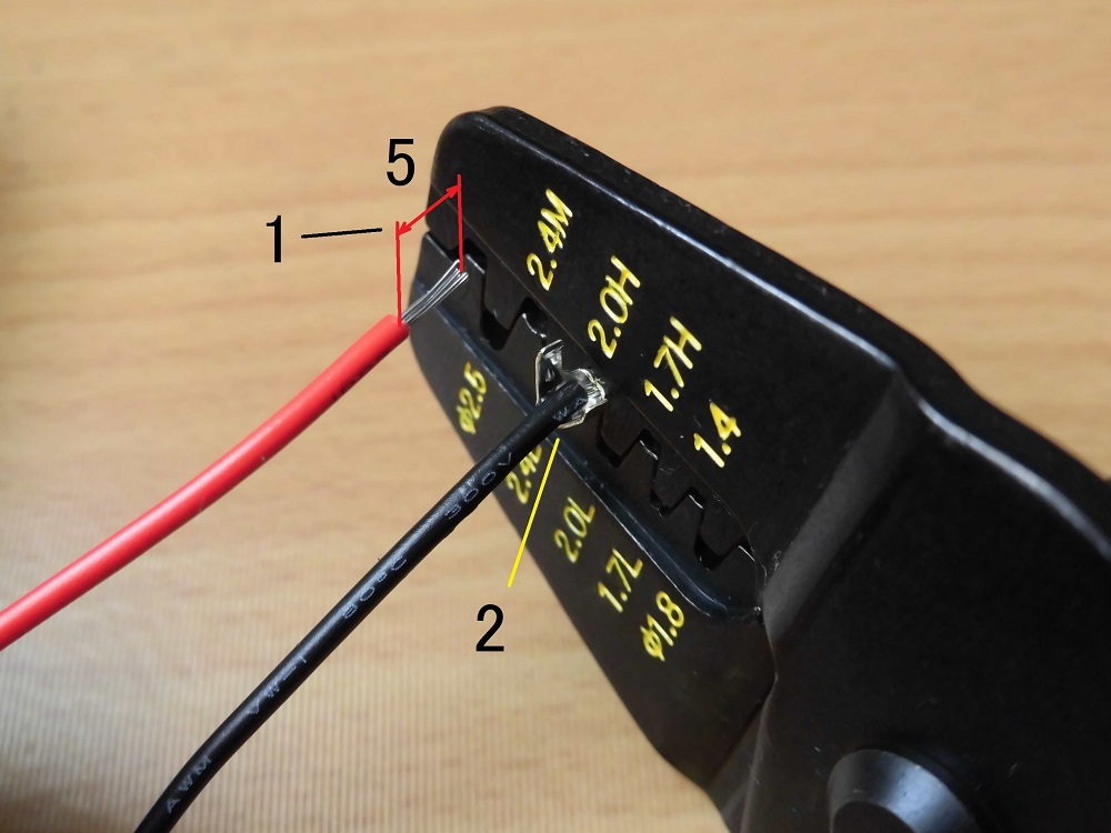
<Crimp terminals>
- Using crimping tool, peel off about 5mm of the outer covering.
- Crimp the terminals with a crimping tool.
Wiring processing 2
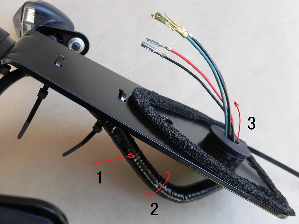
<Wiring processing 2>
Along with the left and right turn signal wires,
- Pass the wires through the corrugated tube.
- Wrap insulation tape around the tube.
- Pass the wires through the grommet.
Install connector
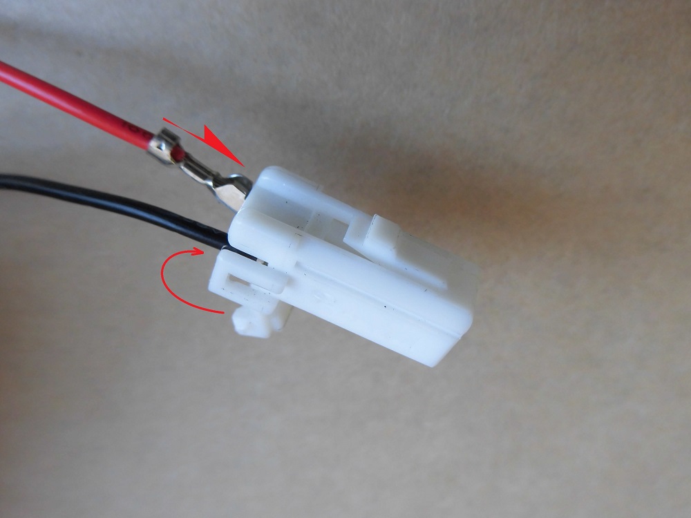
<Install connector>
Insert the terminals into the connector, paying attention to position and orientation, and lock it.
Wiring fixing
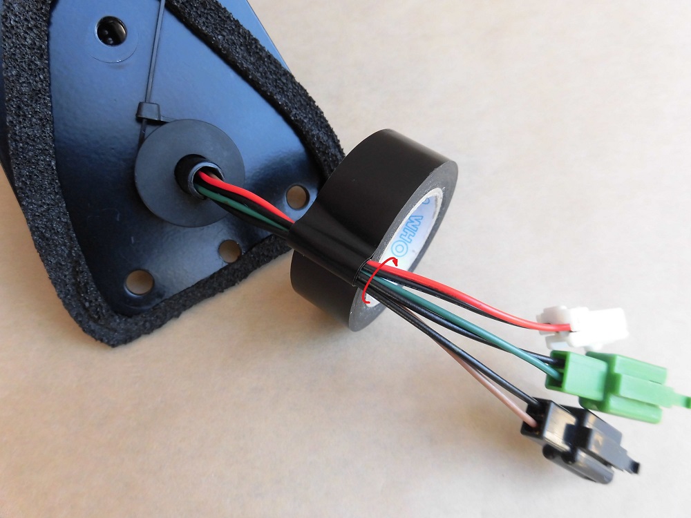
<Wiring fixing>
To prevent the three wires from coming apart, I put them together with insulation tape.
Assembled tail tidy
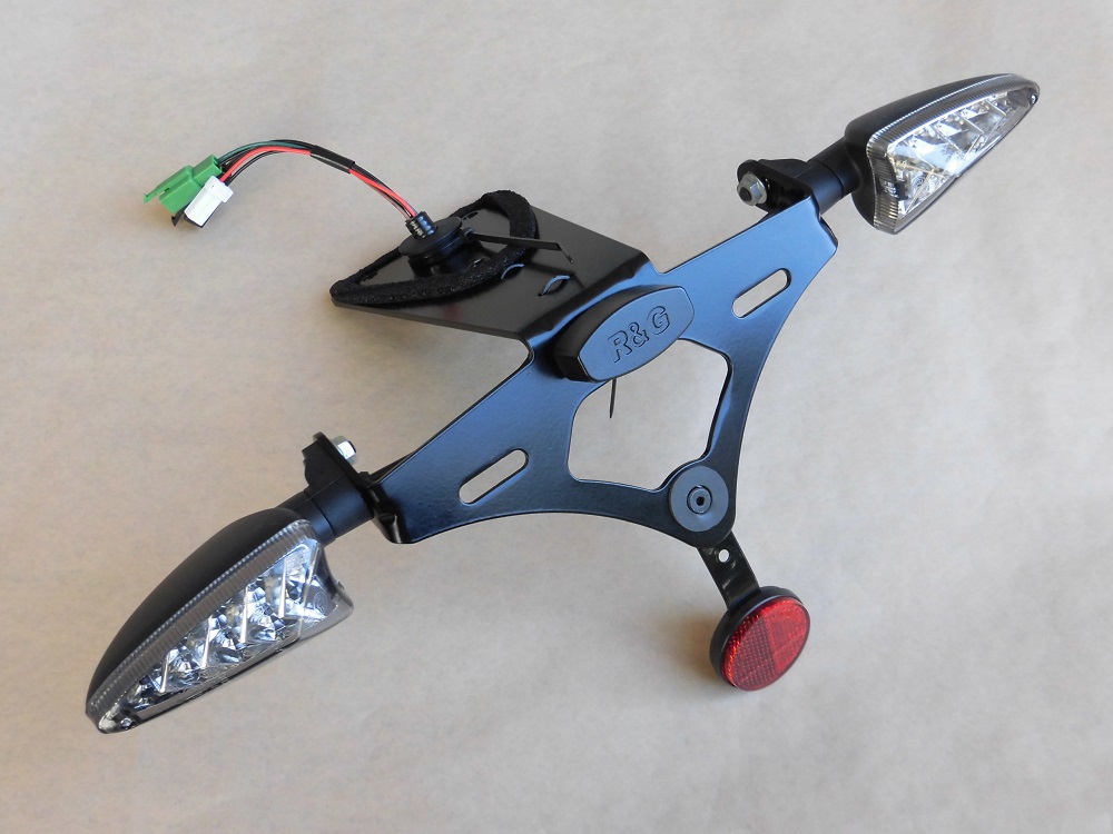
<Front side>
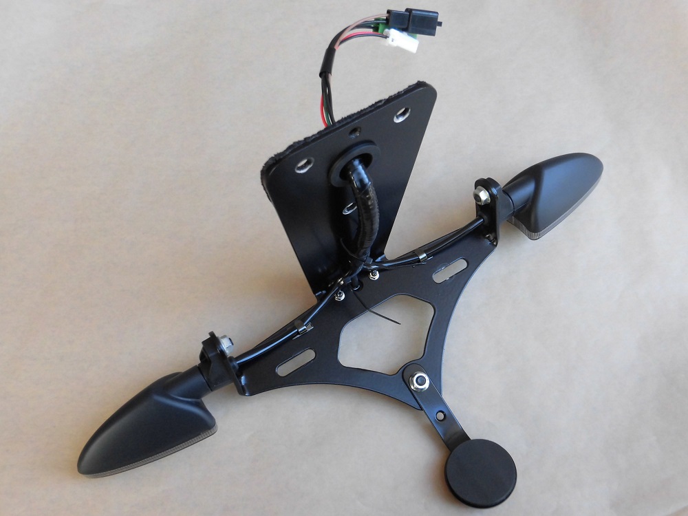
<Reverse side>
The wiring length was shortened, and the wiring was also aligned with the wiring for the turn signals. So, it was much cleaner.
Install tail tidy
Install the tail tidy to the moto body.
(For details, see the maintenance record “Replace tail tidy 4【Installation】”.)
Connect connector
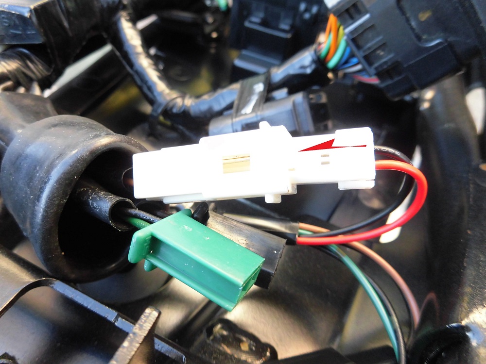
<Connect connector>
Connect the connector to the wiring on the moto body side.
The length is perfect and easy to connect.
Comparison before and after wiring processing
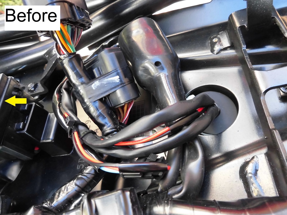
<Before>
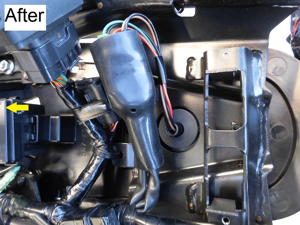
<After>
The engine control unit is lifted in both cases.
The wiring layout has been simplified.
Install rear cowls and panel etc.
The rear cowls and panel, etc. are then installed to complete the process.
(For details, please refer to the maintenance record “How to install rear cowls and panel etc.”)
3. Summary
The license plate light wiring was modified to match the tail tidy.
In addition, I obtained and crimped the terminals of the connector of the genuine part so that it can be removed and installed as if it were a genuine part.
- The wiring length of the license plate light can be cleared up by matching it to the tail tidy.
- I recommend crimping the former AMP070 type female terminals and using the genuine connectors, instead of using the bullet terminals or a connector of general-purpose type.
