I bought a retrofit burglar alarm and a drive recorder.
Both require an electrical signal from the ignition switch OFF (ON), so the ignition power supply (hereinafter described as IG power supply) is taken out from the moto body.
The following methods are available for taking out the IG power supply.
- Using a power supply extraction harness
- From the fuse box
- From the brake light
Other
1 is the most reliable, but unfortunately, I could not find a harness for 5D7 on the market.
Therefore, I will take the IG power from the fuse box in 2.
Since the main body of the electrical component is usually mounted under the seat, I thought it would be best to connect it to the fuse box under the seat.
From this article, you can learn the following.
- How to get IG power supply from a fuse box
- How to make branch wiring with fuse
| Date | 5th March 2022 |
| Subjects | Tuning, Customizing |
| Shop or DIY | DIY |
| Difficulty | |
| Working hours | 2 |
| Costs [Yen] | 319 |
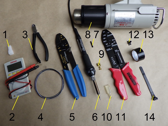
1. Goods to use
| No. | Products name | Manufacturer | Products number | Quantity | Amounts[Yen] | Purchase this time |
| 1 | Fuse clip | – | – | 1 | 87 | |
| 2 | Digital multi meter | SANWA | PM3 | 1 | 4,950 | |
| ST5 | Power supply outlet fuse | MONTARO | 29182214 | 1 | 286 | ○ |
| 3 | Miniature diagonal cutter | HOZAN | N-35 | 1 | 3,465 | |
| 4 | Wiring (1m, black and white) | Sumitomo electronic wiring | AVSSB03f-BKWH | 1 | 160 | |
| 5 | Crimping tool | HOZAN | P-704 | 1 | 5,148 | |
| 6 | Soldering controller | TAIYO ELECTRONIC | PX-601AS | 1 | 17,600 | |
| 7 | Heat shrinks tube (φ2) | – | – | 1 | 74 | |
| 8 | Heating gun | HAKKO | 880B | 1 | (7,260) | |
| 9 | Two-way bullet terminal | YAZAKI | F2YG-sr | 1 | 33 | ○ |
| 10 | Sleeve (For 250 terminal) | – | – | 1 | 384 | |
| 11 | Electric pliers | STRAIGHT | 12-679 | 1 | 630 | |
| 12 | Stainless cable clamp | AMON | 1193 | 1 | (384) | |
| 13 | Insulating tape | OHM ELECTRONIC | DE1910K | 1 | (84) | |
| 14 | Cable ties (Repeatable) | ELPA | KBR-N100015(BK) | 1 | 284 | |
| 40,829 | 319 |
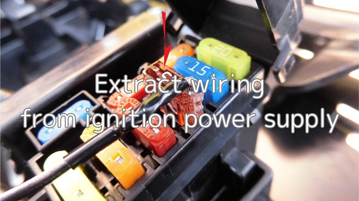
2. Extract wiring from ignition power supply (STEP 1-30)
Remove seat
First, remove the sheet.
*
The box is removed due to other work, but it is easier to work that way.
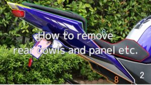
If you want to remove up to the box, please refer to the maintenance record “How to remove rear cowls and panel etc.” STEP 1-21.
Open fuse box lid
<Open fuse box lid>
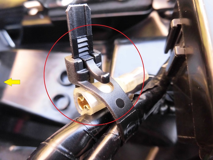
Press the pawl to open the fuse box lid.
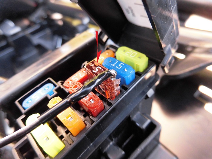
Remove signal fuse
Take the wiring out of the signal fuse (7.5A), which is energized when the ignition switch is turned ON.
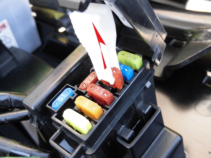
<Remove signal fuse>
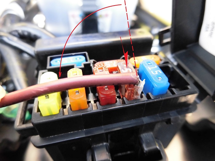
Using the fuse clip, remove the third fuse from the top in the photo.
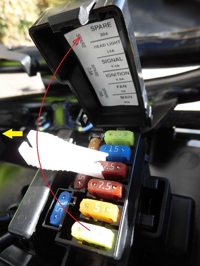
Check direction of electricity flow
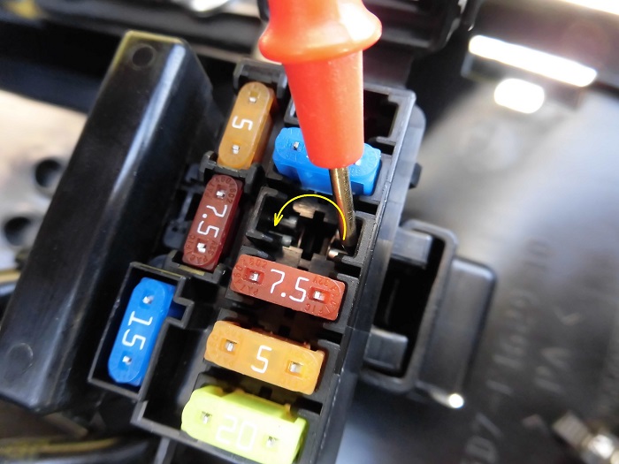
<Check direction of electricity flow>
I checked the direction of electricity flow with a digital multimeter and found that it flows from the rear to the front.
Therefore, I decided to pull out the wiring from the rear of the upstream side.
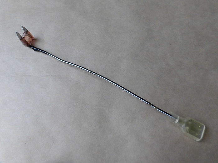
Comparison of old and new fuses
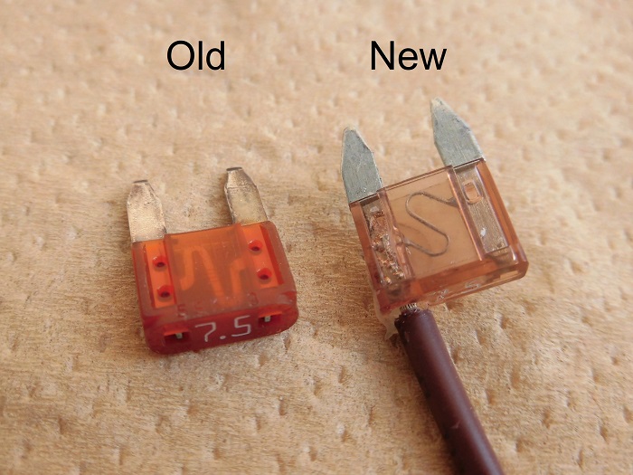
<Comparison of old and new fuses>
Left: Removed, Genuine parts
Right: Installed, Power supply outlet fuse
The power supply outlet fuse has wiring on one side, to which electrical components are connected.
Study of wiring routing 1
The following considerations were made for the installation.
- Do not drill holes in the fuse box.
- The fuse box lid can be closed.
If more electrical components are added in the future, I will consider changing the method so that it can be restored to its original state.
Study of wiring routing 2
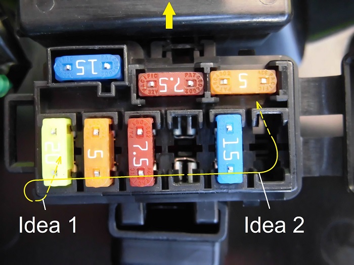
<Study of wiring routing 2>
Idea 1: Pass the wires through the gap in the lid
We are happy to see that there is a small gap where we can pass the wires through.
Idea 2: Through the gap under the spare fuse (20A)
The underside of the spare fuse was open, and there was a gap where the wires could pass through.
Although it is good that we can’t see it from the outside, it is not easy to remove the terminals by crimping them after passing them through the gap. So I decided to go with idea 1.
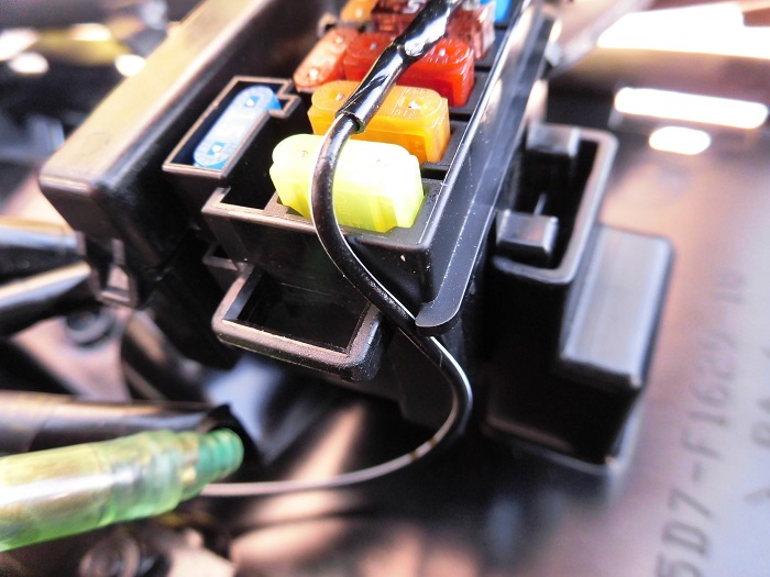
Study of wiring routing 3
<Study of wiring routing 3>
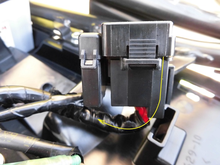
The wiring through the gap in the lid should be routed through the side of the fuse box and along the underside of the fuse box.
Install wired fuse
Now let’s install the fuse with wire.
<Install wired fuse>
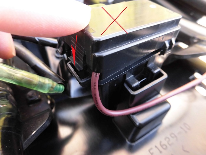
Plug in the wired fuse and bend the wiring 90 degrees.
I feel like I’m straining the wiring as hard as I can…
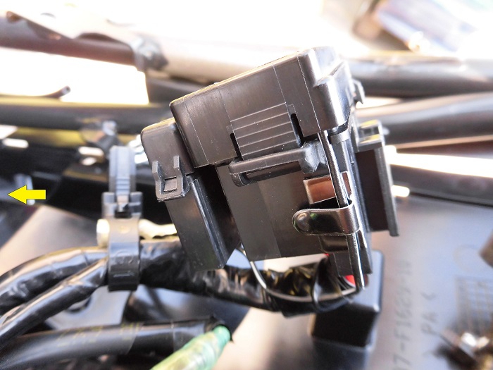
Close fuse box lid
<Close fuse box lid>
I tried to close the fuse box lid, but it wouldn’t close…
It seems that the wiring is too thick to fit in the gap.
I checked and found that the gap between the fuse and the lid is about 2mm, and the outer diameter of the wiring is 2.7mm (0.75sq wire).
I feel that it may be possible to close it by pushing it in, but I wonder if there is any way to do it.
Cut wired fuse
Since the purchased electrical components only take electrical signals, the current flowing through them is considered to be low.
Therefore, the wire does not need to be 0.75sq. So, I decided to replace it with 0.3sq and make the outer diameter of the wiring thinner.
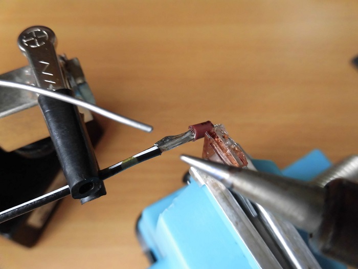
<Cut wired fuse>
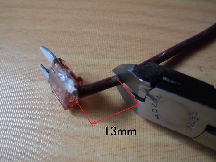
Cut the wired fuse at 13 mm from the fuse.
It would be a waste not to use the fuse (5A) and the connector terminal on the cut wiring side, even though they are also attached…
Remove outer cover of fuse wiring
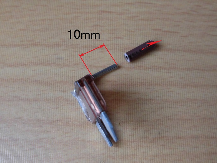
<Remove outer cover of fuse wiring>
Peel off about 10 mm of the outer cover.
Prepare wiring
Prepare 0.3 sq. wiring.
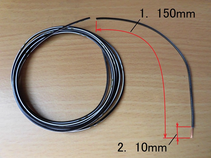
<Prepare wiring>
- Cut a 150 mm length.
- Peel off about 10mm of the outer cover.
Connect wiring
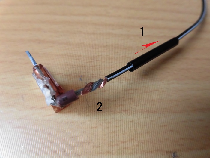
<Connect wiring>
- Pass through 25 mm shrink tube (ø2).
- Pull the wires closer together.
Soldering Failure
I was soldering the yawning part, but I made a painful mistake here.
<Soldering Failure>
When soldering the back side, the wires were not held down and fell the moment the solder melted.
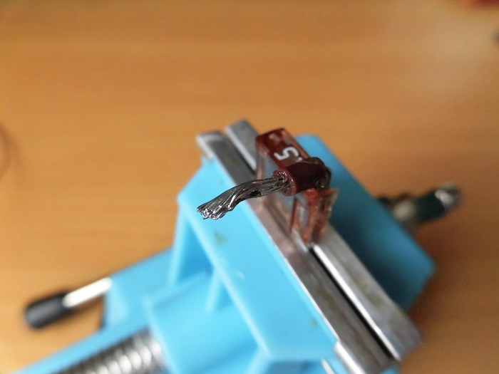
Soldering
<Soldering>
As it was difficult to twist the wires anymore, I soldered them with the wires straightened.
The silicone on the fuse melted out and I had a bit of a scare, but I got it done.
The connection will be weak, but I don’t think it will take much pulling force, so it should be fine.
But the important thing is that the outer diameter has become thicker and larger than expected…
Remove outer cover
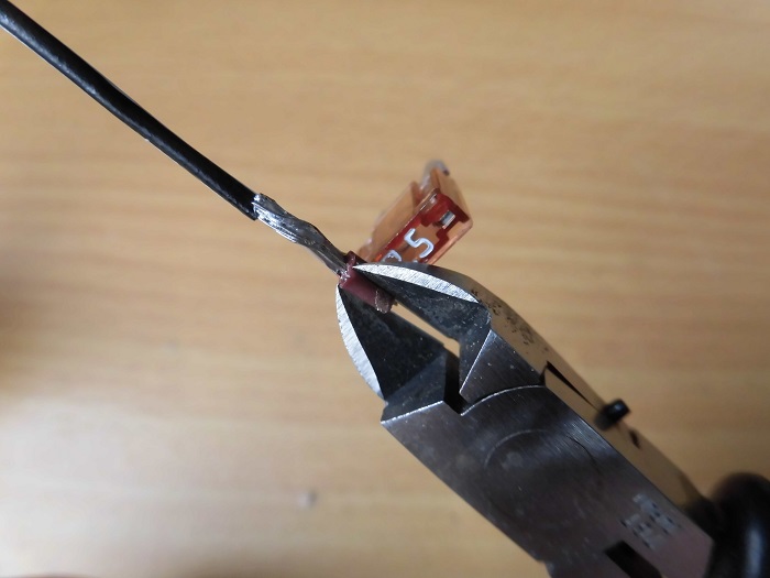
<Remove outer cover>
Using nippers, remove about 3 mm of the outer cover left on the fuse side.
Heat shrinkage
<Heat shrinkage>
Cover with shrink tube and use a heat gun to shrink.
After shrinkage
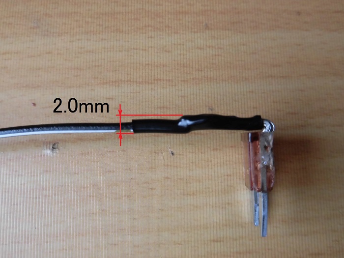
<After shrinkage>
The maximum outside diameter of the wiring is now about 2 mm, a reduction of 0.7 mm from the original 2.7 mm.
It should now fit in the fuse box.
Terminal and sleeve
Next, process the other side of the wiring.
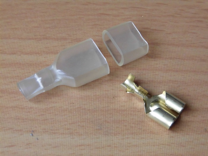
<Terminal and sleeve>
This time, in order to be able to connect two electrical components, I prepared 2-way bullet terminal.
The sleeve is for flat terminals and are cut short.
However, I realized later that I did not need to cut the sleeve.
I thought that the long sleeve would be a nuisance when connecting the terminals, but it was only necessary to move the sleeve…
Crimp terminal 1
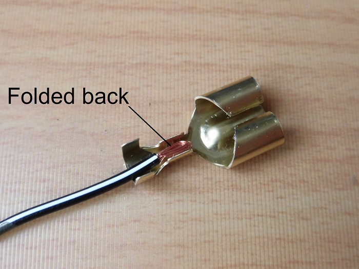
<Crimp terminal 1>
Since 0.3sq is not enough wire width for the part to be crimped, the wiring is folded back.
Crimp terminal 2
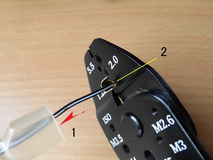
<Crimp terminal 2>
- Thread the sleeve
- Crimp with electric pliers
Install sleeve
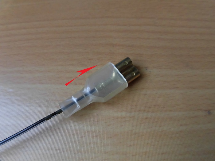
<Install sleeve>
Pass the sleeve through the terminal.
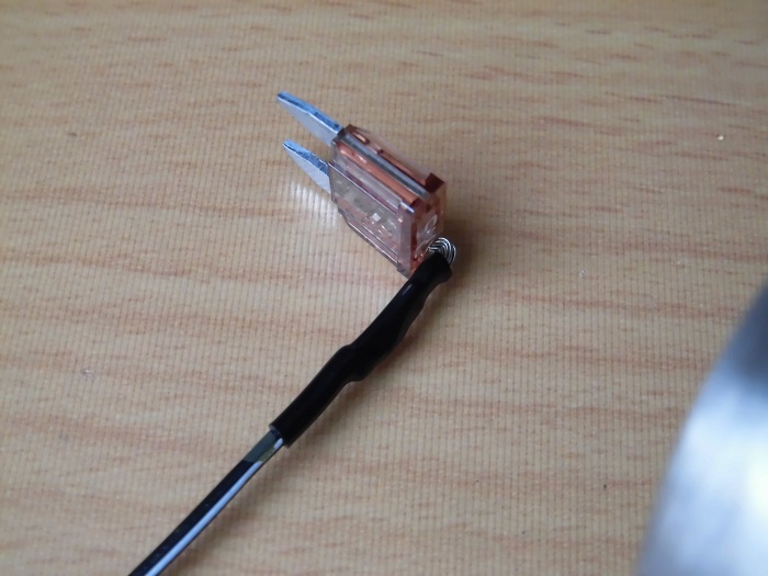
Branch wiring
<Branch wiring>
The finished product looks like this.
I cut the sleeve too short, and when I move the terminal, it sticks out of the sleeve by about 0.5mm.
I didn’t expect the sleeve to move so much…
I knew I shouldn’t have cut it.
Install branch wiring
Now, install it in the fuse box.
<Install branch wiring>
Insert the branch wiring fuse into the fuse box.
Wiring layout
<Wiring layout>
The wires, now thinner and easier to bend, are placed along the edge of the fuse box.
The fuse box lid is now safely closed.
Fix wiring 1
<Fix wiring 1>
Then, the wiring is;
- Fixed with cable clamp attached to the side of the fuse box.
- Fix the wires with insulating tape along the wiring under the fuse box.
Fix wiring 2
<Fix wiring 2>
Finally, use a reusable cable tie to secure the 2-way bullet terminal.
This will be useful for connecting and disconnecting the connectors.
Connected branch wiring
<Connected branch wiring>
It was a bit of a feather in the cap, but I managed to get it installed.
Now, I can install the electrical components I purchased anytime I want.
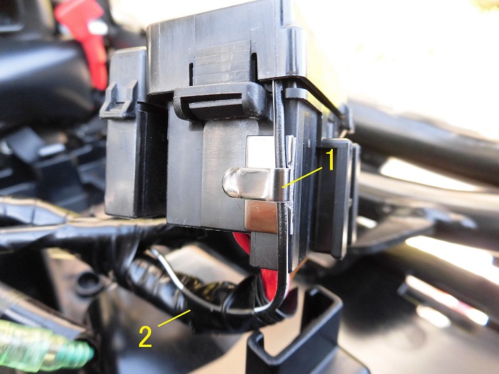
Fuse box lock
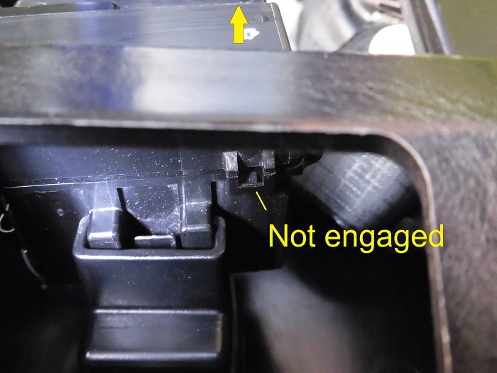
<Fuse box lock>
However, I later noticed that the lock on the back of the fuse box was not engaged.
I knew there was a strain on the lid…
3. Summary
In this article, I have summarized how to take IG power supply out of the fuse box and how to make branch wiring.
If the fuse blows, I have to rebuild it, but even now, more than 3 years later, it is still working fine.
- Ignition power supply can be taken from the signal fuse (7.5A)
- Signal fuse (7.5A) is powered from the rear to the front.
- The fuse box lid could not be closed with the commercially available power supply outlet fuse because of the thicker linearity of the outer cover.
- After replacing the wiring of the power supply outlet fuse with 0.3sq, the fuse box lid could be closed.