This fourth installment covers the fabrication of a bracket for the drive recorder switch.
To mount it in the location decided in the maintenance record “Motorcycle Dash Cam Installation 1 – Planning the Setup”, I focused on the following points:
- Ensure the bracket’s shape and position do not interfere with the lever holder or bolt
- Determine how the switch will be secured
To create a 4mm offset, I prioritized ease of processing and used a 1.2mm aluminum sheet I had on hand.
From this article, you’ll learn:
- How to make a bracket for a drive recorder switch
- How to mount the bracket to the vehicle and secure the switch
| Date | 8th April 2023 |
| Subjects | Tuning, Customizing |
| Shop or DIY | DIY |
| Difficulty | |
| Working hours | 12 |
| Costs [Yen] | 0 |
Although the work date is listed as 8 April, 2023, the actual work was carried out over several days.
1. Goods to use
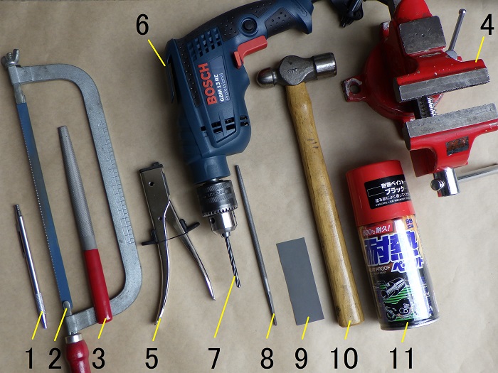
| No. | Products name | Manufacturer | Product number | Quantity | Amounts[Yen] |
| ST2 | Aluminum sheet (1.2mm) | HIKARI | HA1213 | 1 | 494 |
| 1 | Pencil-type scriber | STRAIGHT | 19-640 | 1 | 980 |
| 2 | Handsaw | – | – | 1 | 670 |
| 3 | Metal file | – | – | 1 | 417 |
| 4 | Vice 90mm | Fujiwara Industrial | 220915 | 1 | (4,398) |
| 5 | Hand nibbling tool | Three axis | 11334 | 1 | 2,748 |
| 6 | Power drill | Bosch | GBM13RE | 1 | 22,880 |
| 7 | Drill (7 and 5, 2.5mm) | – | – | 1 each | 579 |
| 8 | Round file | – | – | 1 | 384 |
| 9 | Waterproof sandpaper (#800) | TAKAGI | – | 1 | 148 |
| 10 | Hammer | – | – | 1 | 1,648 |
| 11 | Heatproof paint Black | SOFT99 | 08020 | 1 | 1,538 |
| ST15 | Compact curing oven | CARVEK | 1026 | 1 | 20,350 |
| 57,234 |
2. Crafting the Switch Bracket (STEP 1–17)
Sample made from cardboard
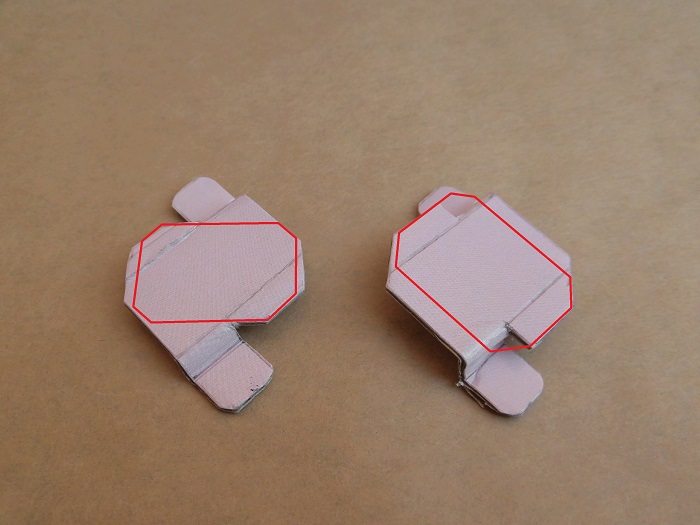
<Sample made from cardboard>
Just like with the camera bracket, I made a cardboard sample by holding it up to the vehicle and adjusting the shape and position.
This sample will serve as the template for the aluminum version.
Left: Switch mounted at an angle
Right: Switch mounted straight
Tightening the bolt is easier on the left, but cable routing is better on the right.
After some deliberation, I decided to go with the angled (left) version.
Marking the aluminum plate
Let’s begin the work.
Using a scriber, I marked the aluminum sheet for:
- Cutting lines
- Bending lines
- Drill hole positions
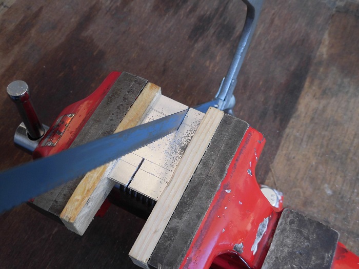
Cutting the aluminum sheet 1
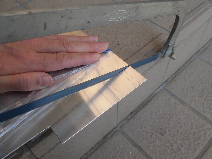
<Cutting the aluminum sheet 1>
I used a handsaw to cut the sheet.
It wasn’t a large cut, but the blade seemed worn, so it took longer than expected.
I think I wrote something similar when making the camera bracket…
Cutting the aluminum sheet 2
<Cutting the aluminum sheet 2>
I cleaned up the saw edges with a file.
Removed major irregularities and burrs.
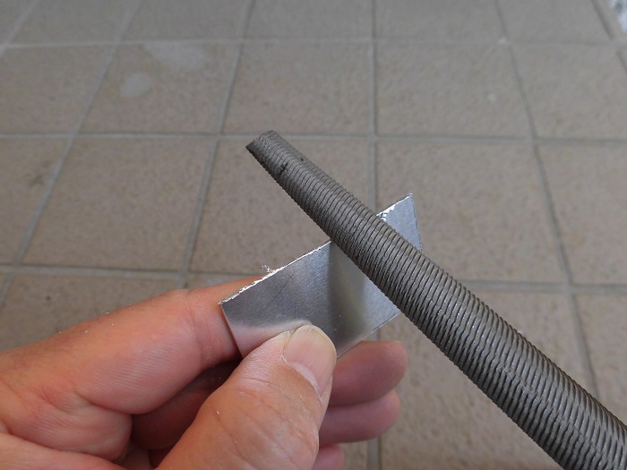
Cutting the aluminum sheet 3
<Cutting the aluminum sheet 3>
I made notches where the bends will go.
Cutting the aluminum sheet 4
After STEP 5, I realized filing the notched areas would be tricky…
<Cutting the aluminum sheet 4>
So, I used a hand nibbler to create grooves.
I also trimmed off excess material.
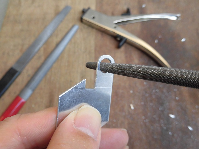
Drilling the aluminum sheet 1
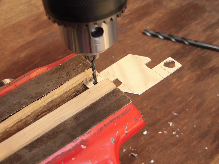
<Drilling the aluminum sheet 1>
I drilled two holes for bolts.
Since the sheet is thin, I gradually widened the holes from 2.5mm to 7mm to prevent the drill from catching.
In hindsight, it would’ve been better to drill before STEP 5.
Drilling the aluminum sheet 2
<Drilling the aluminum sheet 2>
I filed the drilled holes to remove burrs and refine the shape.
Finishing the edges and surface
Before bending, I finished the edges and removed fine scratches from the surface caused during processing.
This also helps with paint adhesion.
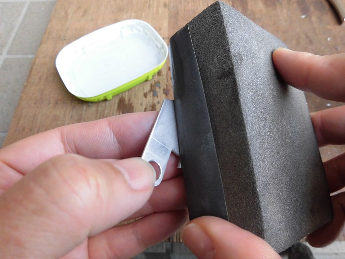
<Finishing the edges and surface>
I sanded with #800 grit paper.
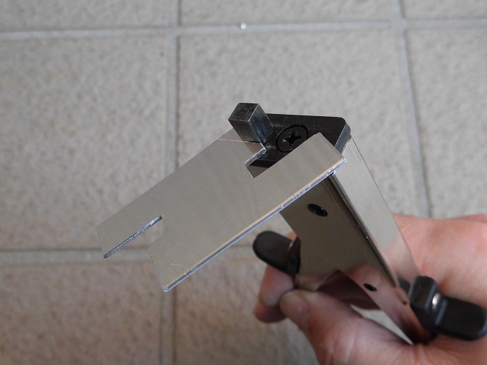
Processed aluminum sheet
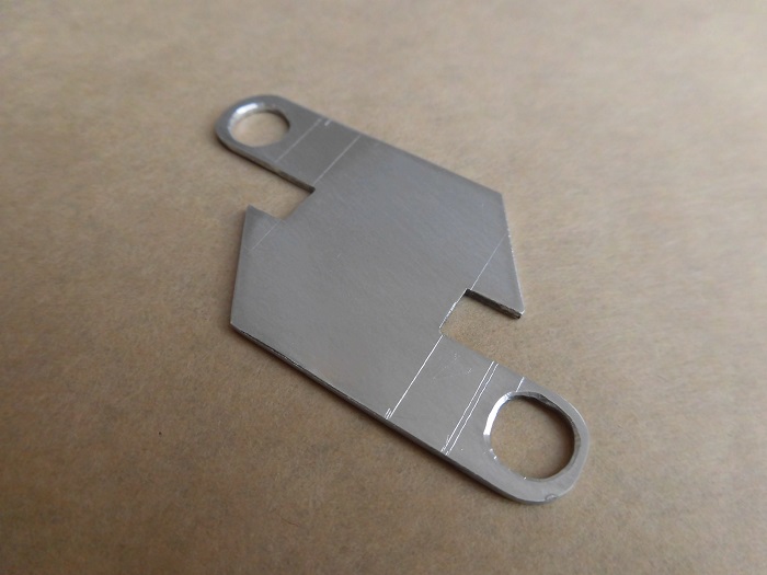
<Processed aluminum sheet>
Here’s how it turned out.
The hole shapes are a bit wonky.
Bending the aluminum sheet 1
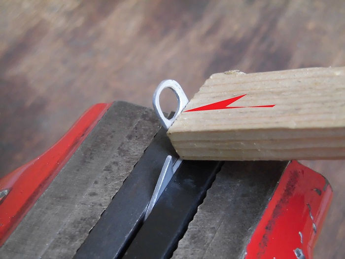
<Bending the aluminum sheet 1>
I clamped the aluminum sheet in a vise and bent it with a hammer.
To avoid surface damage, I sandwiched it between flat bars instead of clamping directly.
Finished bracket
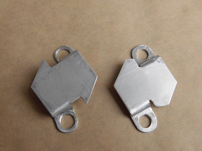
<Finished bracket>
In the end, I made two brackets.
Left: First attempt (failed)
Right: Second attempt
The first one failed because:
- Initial measurements were sloppy
- I didn’t account for sheet thickness, so the overall length and height were off
As a result, the hole positions didn’t align.
I forced it onto the lever holder, which caused it to bend.
For the second one, I finalized the dimensions and drilled 6mm holes (for M6 bolts).
Note: Photos from STEP 3–11 are of the first bracket.
I didn’t have the mental bandwidth to take photos during the second attempt…
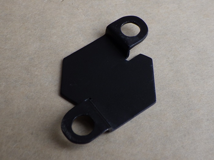
Second bracket
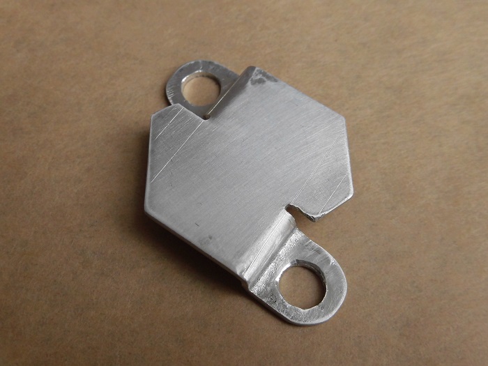
<Front side>
Zooming in, you can see the chamfering and other details are a bit rough.
Let’s call it handmade charm.
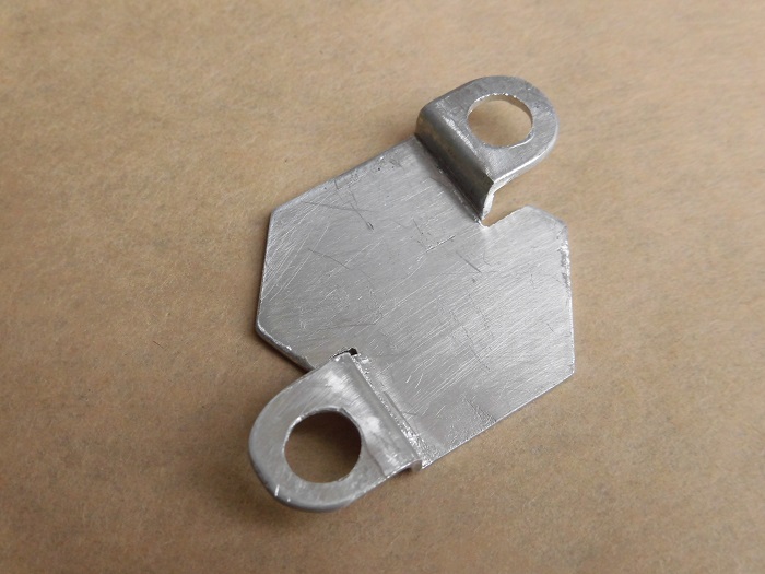
<Back side>
Raised about 4mm.
Bracket painting
Next, I painted the bracket to finish it.
<Bracket painting>
My go-to black heat-resistant paint.
I use it because baking improves paint adhesion.
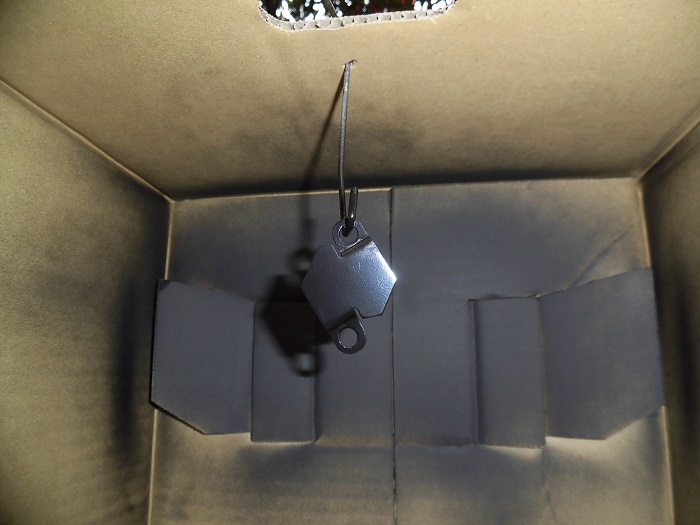
Baking the paint
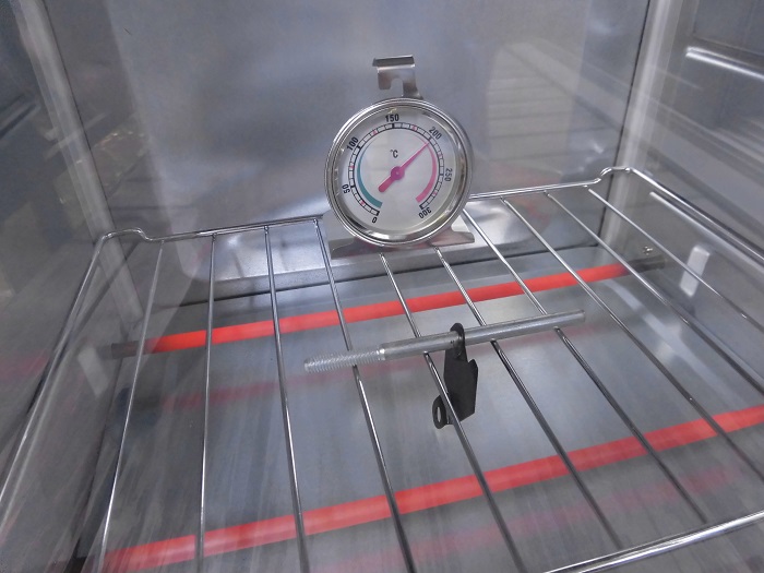
<Baking the paint>
I baked it in a curing oven at 150°C for one hour.。
Painted bracket
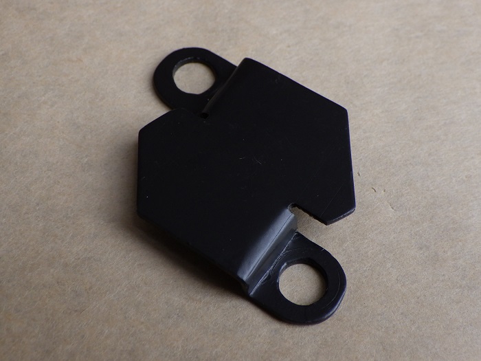
<Front side>
Here’s the finished look.
<Back side>
Baked paint seems to hide unevenness well.
Most of the bracket will be hidden by the switch and bolts anyway, so paint quality isn’t a big concern.
Switch mounted
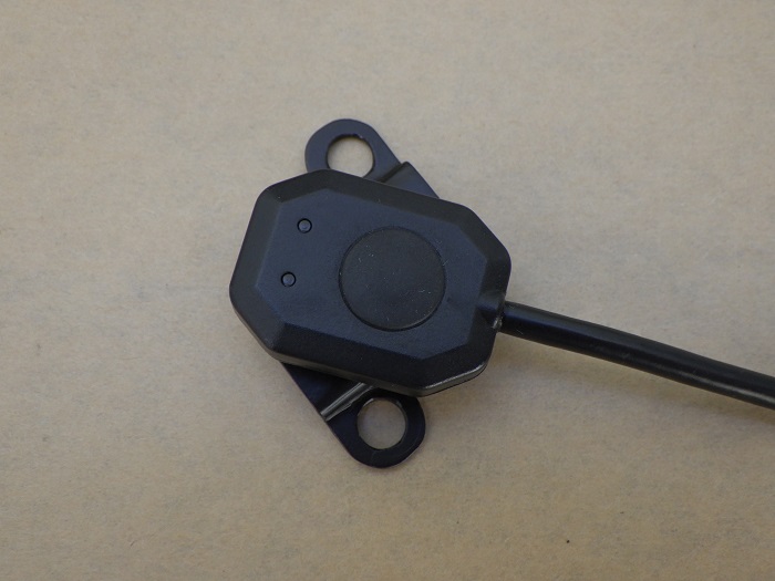
<Switch mounted>
This is how I plan to install it.
Continued in the maintenance records “Motorcycle Dash Cam Installation 5 –Installing the Main Unit”.
3. Summary
Here’s a summary of the bracket fabrication process for the drive recorder switch.
One benefit of DIY is being able to freely choose the bracket shape to match the switch design and mounting orientation.
- Prioritized ease of processing and used 1.2mm aluminum sheet
- For thin sheets, start with small holes and gradually enlarge them
- Created a 4mm offset to avoid interference with the lever holder
- Bending makes hole alignment tricky—consider drilling after bending
- Baking the paint improves adhesion