This is a continuation of “Motorcycle Dash Cam Installation 5 – Installing the Main Unit”.
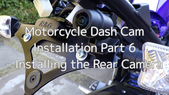
In this sixth installment, we’ll be installing the rear camera.
The drive recorder used is the Mitsuba Sankowa / EDR-21A.
Since the fender has been replaced with an R&G tail tidy / LP0162BK, the rear camera will be mounted on that.
From this article, you’ll learn:
- How to install the rear camera and bracket
- How to route the rear camera wiring
- Additional tasks required for installation
| Date | 3rd December 2023 |
| Subjects | Tuning, Customizing |
| Shop or DIY | DIY |
| Difficulty | |
| Working hours | 3 |
| Costs [Yen] | 670 |
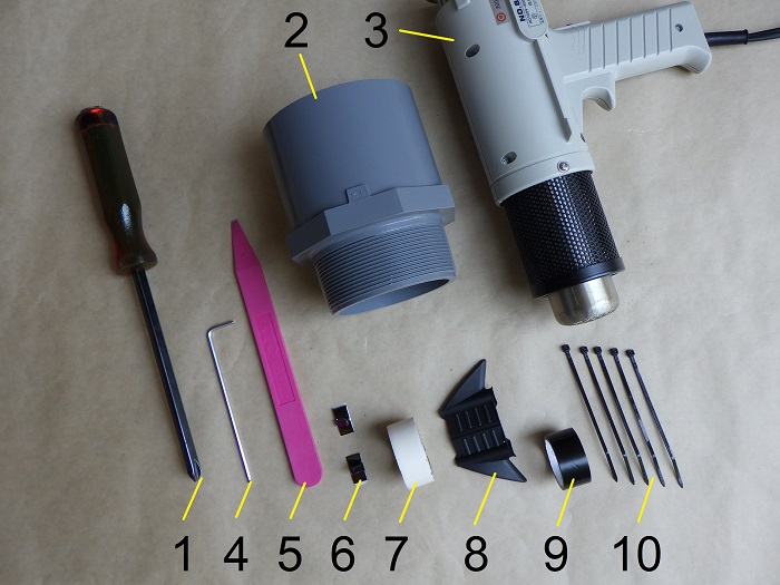
1. Goods to use
| No. | Product name | Manufacturer | Product number | Quantity | Amounts[Yen] | Purchase this time |
| ST1 | Dual-channel motorcycle dash cam | Mitsuba Sankowa | EDR-21A | 1 | 39,380 | |
| ST4 | Well nut (M6, C-630) | KITAKO | 0900-678-05070 | 2 | 325 | ○ |
| ST4 | Pan head screw (M6×20mm) | – | – | 2 | 286 | |
| 1 | Phillips screwdriver (No.3) | KTC | PDD1-3 | 1 | (2,299) | |
| 2 | PVC pipe fitting | – | TS-VS-75 | 1 | 934 | |
| 3 | Heat gun | HAKKO | 880B | 1 | (7,260) | |
| 4 | Long hex key (2.5mm) | KTC | HLD250-2.5 | 1 | 1,122 | |
| 5 | Handy remover | KTC | AP201-HN | 1 | 1,166 | |
| 6 | Wiring clip | AMON | 3421 | 2 | 345 | ○ |
| 7 | Vinyl tape (White) | – | – | 1 | 84 | |
| 8 | Wire insertion tool | Straight | 35-1900 | 1 | 240 | |
| 9 | Insulation tape | OHM | DE1910K | 1 | (84) | |
| 10 | Cable ties (2.5mm) | ELPA | KBF-N100100(BK) | 5 | 175 | |
| 53,700 | 670 |
2. Installing the Rear Camera (STEP 1–24)
Parts to be Installed
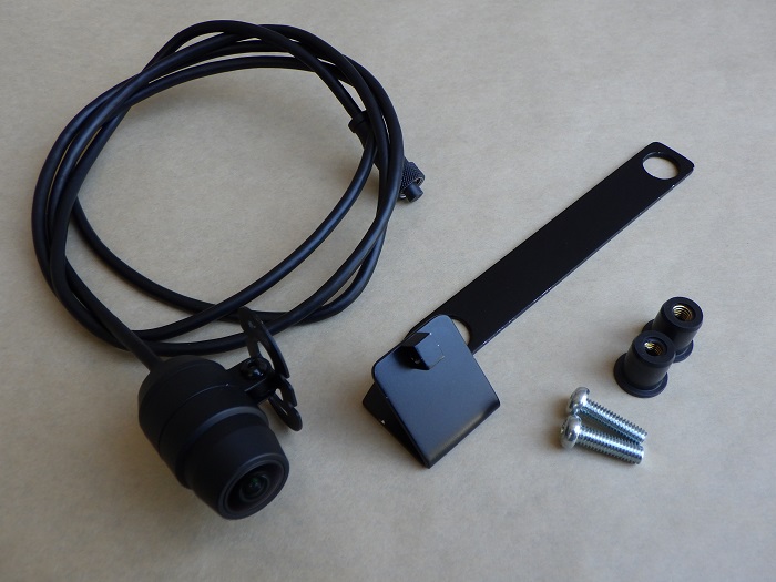
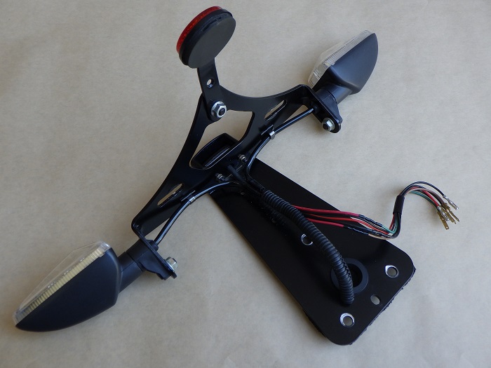
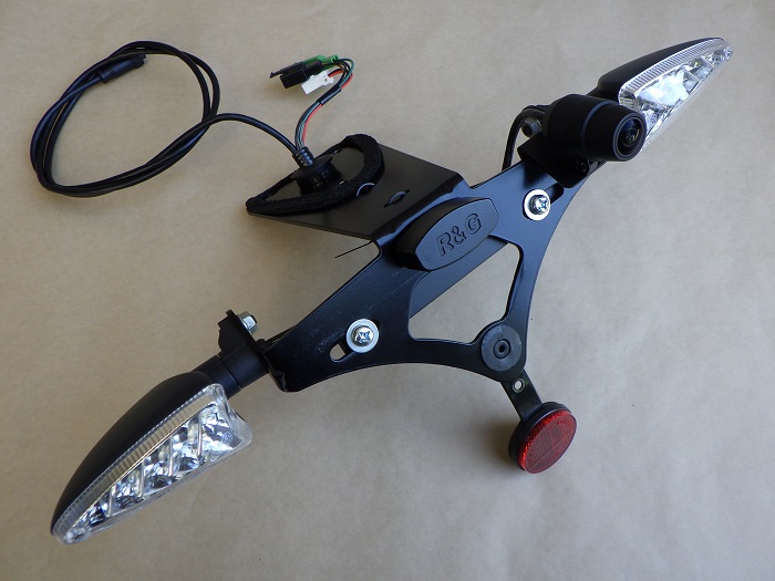
<Parts to be Installed>
The following parts will be used.
From left to right:
- Rear camera
- Rear camera bracket
- Well nut and bolt to secure the rear camera bracket
For bracket fabrication, refer to the maintenance records: Motorcycle Dash Cam Installation Part 3 – Crafting the Camera Brackets.
Tail Tidy Removal 1
To bundle the wiring together, the tail tidy is temporarily removed.
<Tail Tidy Removal 1>
- Remove the burglar alarm along with its bracket (aftermarket part)
- Lift the engine control unit
- Disconnect three connectors
(Some photos may be unclear—thanks for your understanding.)
Then, remove the three bolts securing the tail tidy. The entire unit, including wiring, will drop down.
Tail Tidy Removal 2
To bundle the rear camera cable with other wires (license plate light, left/right turn signals), remove related wiring components.
(For details, refer to the maintenance record: How to remove and install rear turn signals.)
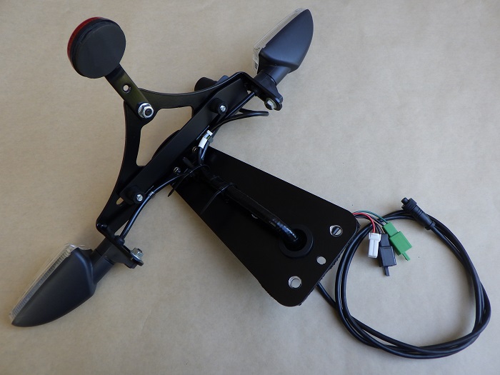
<Tail Tidy>
All necessary components have now been removed.
Rear Camera Bracket Preparation
Let’s begin installing the rear camera.
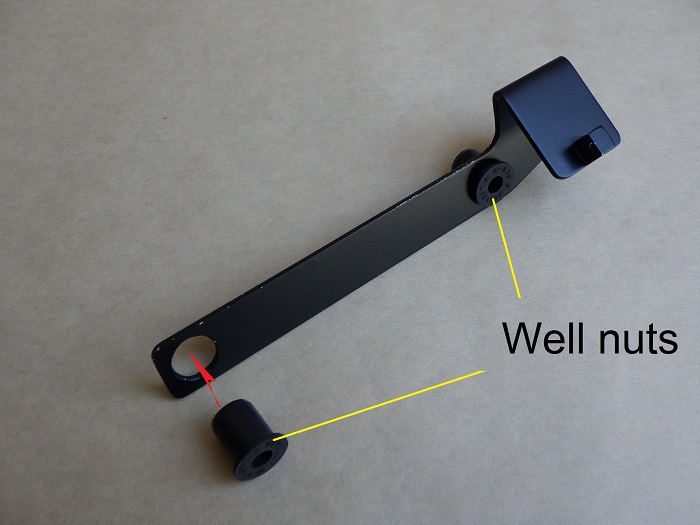
<Rear Camera Bracket Preparation>
Attach an M6 well nut to the rear camera bracket.
The bracket has a φ13 hole to accommodate the well nut.
The well nut was chosen to help dampen vibrations from the R125.
Rear Camera Bracket Installation
Mount the rear camera bracket inside the tail tidy.
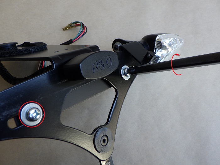
<Rear Camera Bracket Installation>
Use a No.3 Phillips screwdriver to tighten the screw and compress the well nut.
Installed Rear Camera Bracket
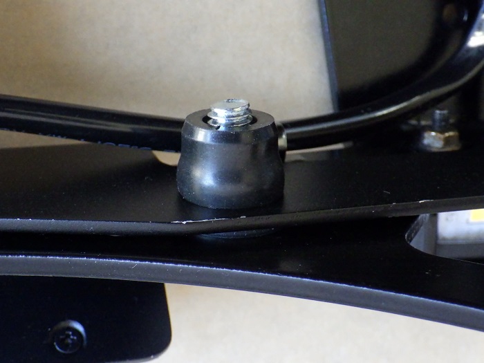
<Installed Rear Camera Bracket>
Here’s how it looks when secured.
Normally, it’s more efficient to work with the license plate still attached, but it was removed for photography.
That said, the bracket paint peels off far too easily.
Despite applying three coats, it’s likely a bonding issue with the aluminum rather than paint thickness.
During STEP 10, the peeling became noticeable, so the paint was stripped and reapplied using heat-resistant paint.
(This part is omitted.)
Cable Heating
Before installing the rear camera, remove the coiled memory from the wiring.
The cable was already wavy when purchased—not due to long-term storage.
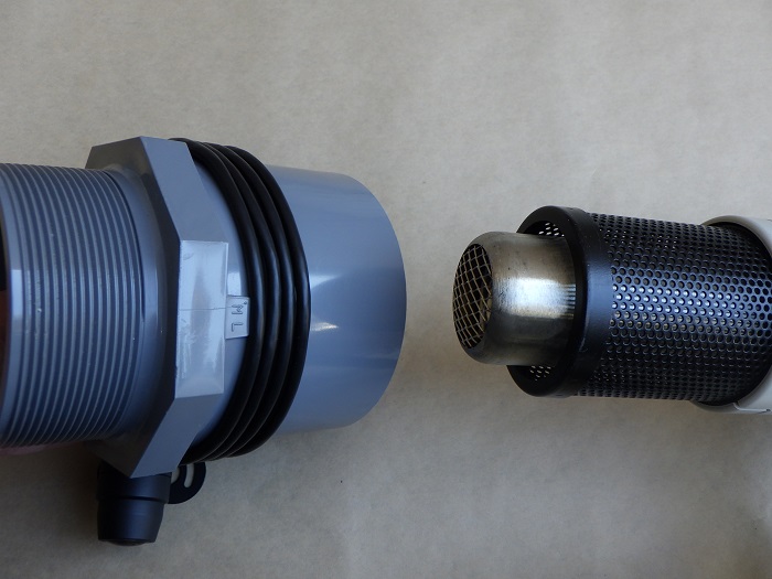
<Cable Heating>
Wrap the cable around a PVC pipe fitting and evenly heat it with a heat gun.
Before and After Heating Comparison
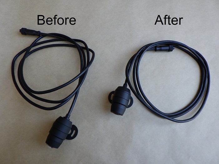
<Before and After Heating Comparison>
Left: Before heating
Right: After heating
It seems slightly improved.
So, the same method was used for the other camera and switch wiring.
Camera Mount Removal
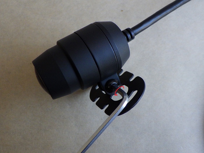
<Camera Mount Removal>
Use a 2.5mm hex wrench to remove the screws securing the camera and its mount.
Since a base was added to the bracket, only the camera, camera ring, and M4 screw are used.
Rear Camera Installation
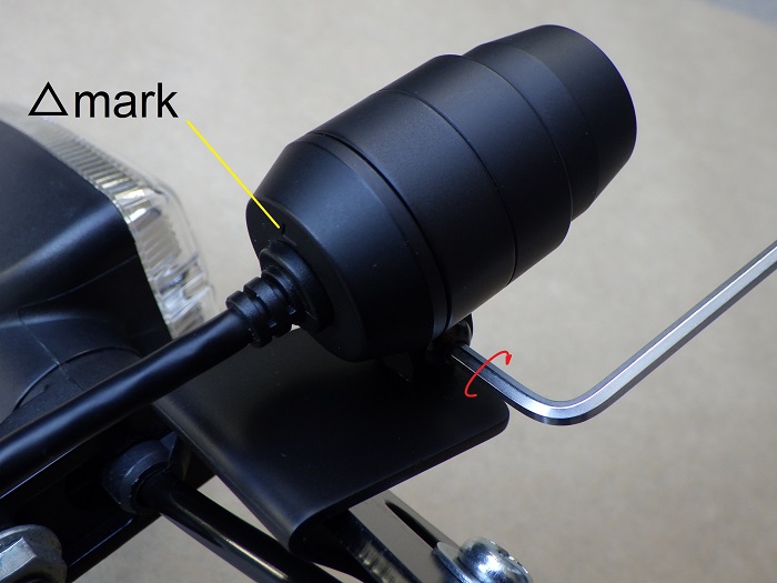
<Rear Camera Installation>
Secure the camera to the bracket base.
As for the camera’s rotation, align the triangle mark upward at this stage.
Vertical orientation will be adjusted after mounting to the bike.
Removing Wiring Clip
The rear camera wiring will be fastened together with the right rear turn signal wiring.
The existing clip is too small, so it will be replaced with a larger one.
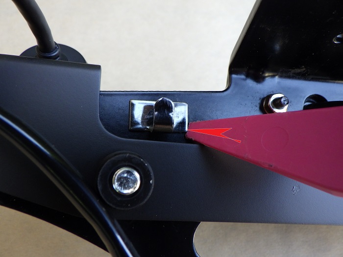
<Removing Wiring Clip>
Since the clip is attached with double-sided tape, use a handy remover to push and peel it off.
Then clean the area with a microfiber cloth.
Wiring Clip Comparison
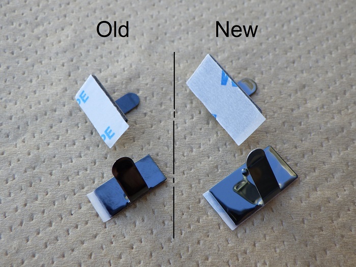
<Wiring Clip Comparison>
Left: Removed part (Amon #1193, photo shows new ones)
Right: Replacement part (Amon #3421)
The size difference is significant.
Wiring Clip Installation
Check the routing of the rear camera and right rear turn signal wiring, then decide on the mounting position.
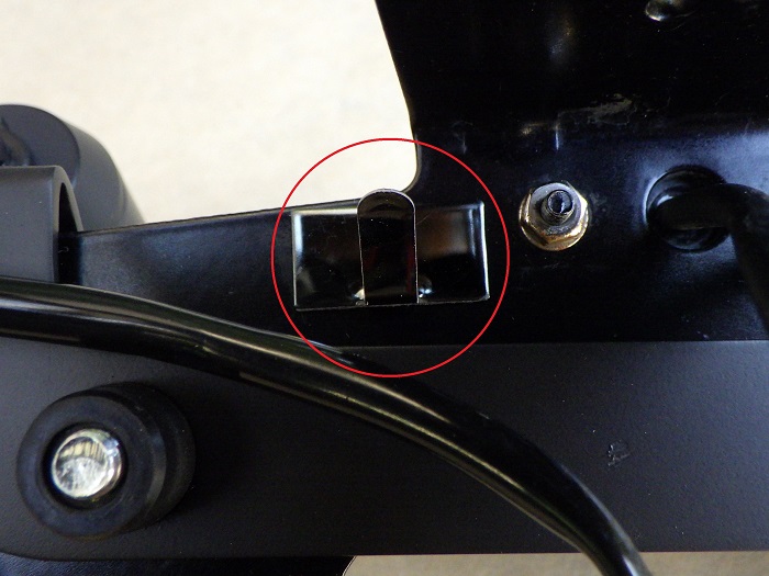
<Wiring Clip Installation>
Peel off the backing of the double-sided tape and attach the clip to the tail tidy.
Wiring Fixation 1
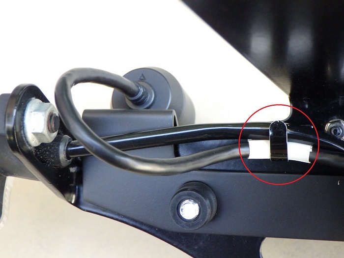
<Wiring Fixation 1>
Clamp the rear camera and right rear turn signal wiring into the clip to secure them.
If the rear camera cable is bent too sharply:
- It may strain the cable
- It may come loose from the clip
- The cable surface may be abraded by the clip
So, some slack was left.
White tape was added to mark the clip position for future maintenance.
Even though a larger clip was chosen, it still feels undersized.
Corrugated Tube Installation
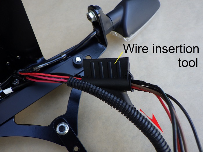
<Corrugated Tube Installation>
Use a wire insertion tool to pass the wiring through a 120mm corrugated tube.
The tube is reused.
Thanks to the thin turn signal wiring, it just fits inside the φ7 tube.
Wrapping with Insulation Tape
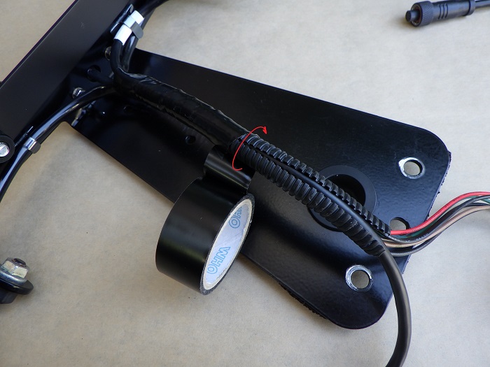
<Wrapping with Insulation Tape>
Wrap insulation tape over the entire corrugated tube, overlapping halfway from the cable base.
Wiring Fixation 2
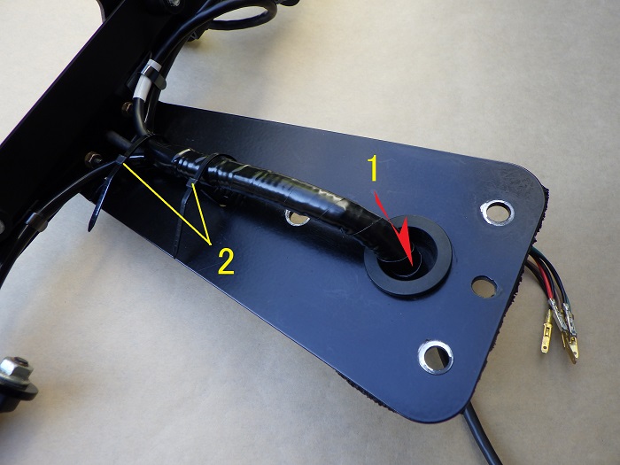
<Wiring Fixation 2>
- Pass the cable and corrugated tube through the grommet
- Temporarily fasten two cable ties to secure the tube
Since the bolt position overlaps with the tube, final tightening will be done after mounting to the bike.
Then, connect three terminals with connectors.
Assembled Tail Tidy
<Front View>
The rear camera seems to be mounted naturally.
Weight increase: 117g
<Rear View>
The rear camera cable is quite long.
Since the tail tidy shortens the wiring compared to stock, the excess cable stands out.
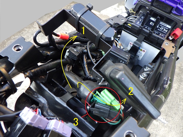
Cable Bundling 1
Mount the tail tidy to the bike and connect the three wires (excluding the rear camera).
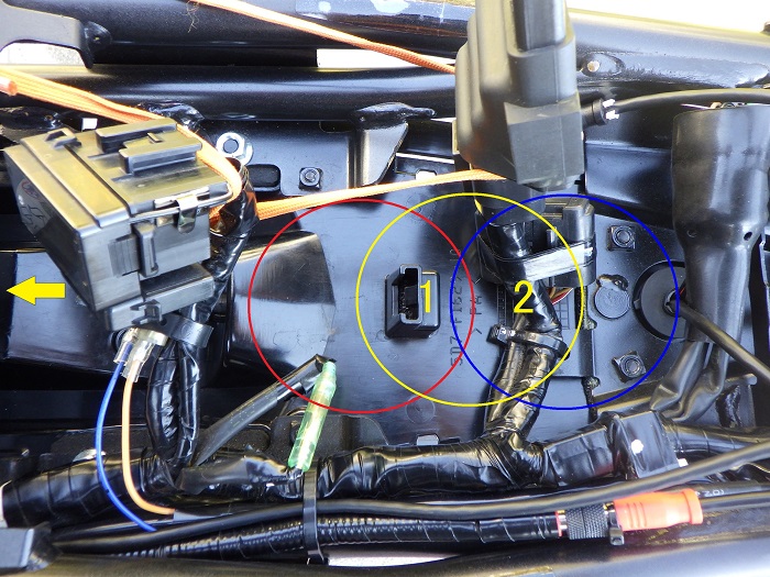
<Cable Bundling 1>
While considering the connection between the rear camera and main unit wiring, bundle the excess cable above the mud flap.
Tested three routing options centered around:
- Fuse box
- Engine control unit wiring
(Locations: red, blue, yellow)
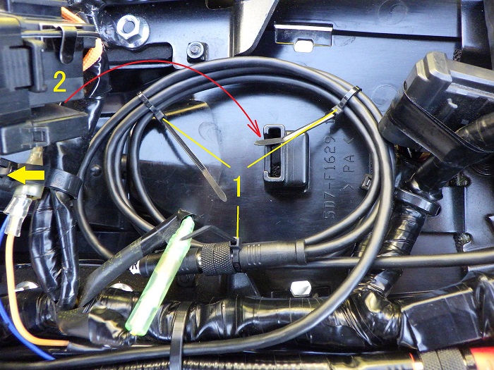
Cable Bundling 2
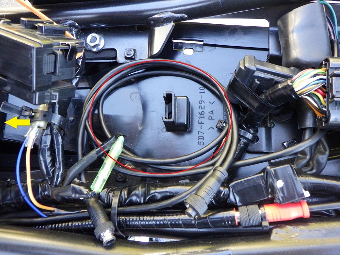
<Cable Bundling 2>
Result: Bundling around the red (fuse box) gave the best fit for the connector and cable layout.
Connecting Intermediate Connector
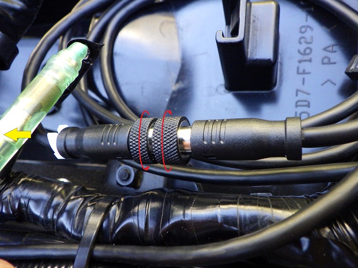
<Connecting Intermediate Connector>
Connect the intermediate connector for the rear camera cable.
Same method as the power cable.
Cable Bundling 3
<Cable Bundling 3>
- Secure the bundled cable with three cable ties
- Restore the fuse box
Wrapping a cable tie around the connector recess helps prevent loosening.
Bundled Cable
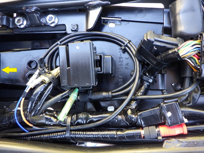
<Bundled Cable>
Here’s how the cable looks when bundled.
The cable routing feels natural from both the main unit and rear camera sides.
However, the cable rattles slightly.
If it causes noise while riding, the fixation method will be reconsidered.
Installed Rear Camera
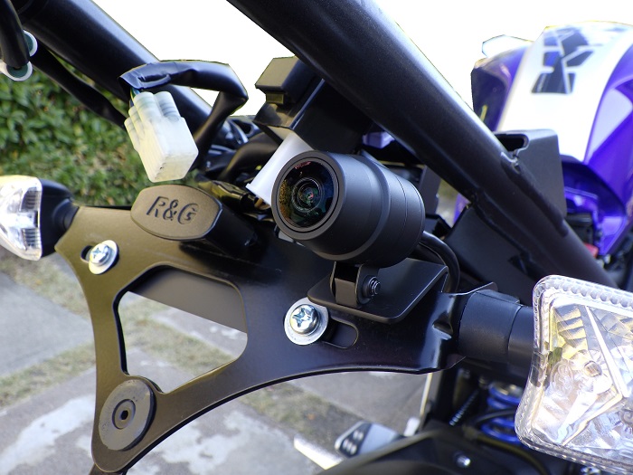
<Installed Rear Camera>
The tail tidy is temporarily mounted, but here’s the result.
Continued in the maintenance record “Motorcycle Dash Cam Installation Part 7 – Installing the Front Camera”.
3. Summary
This article summarized the process of installing the rear camera for the drive recorder.
By routing the rear camera wiring through the same corrugated tube as the turn signal and license plate light wiring, the aftermarket look is minimized.
Additionally, the setup allows the entire tail tidy to be removed from the bike for easier maintenance.
- Removing the tail tidy improves workability
- Well nuts were used to reduce vibration to the camera
- Heating the cable helps reduce coiled memory
- Leave some slack behind the rear camera cable
- Wrapping cable ties around the connector recess helps prevent loosening