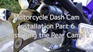
This is a continuation of “Motorcycle Dash Cam Installation 6 – Installing the Rear Camera”.
In this seventh installment, I’ll walk through the process of installing the front camera.
The drive recorder used is the Mitsuba Sankowa / EDR-21A.
I’ll mount a custom-made bracket to the front cowl (right front side) and secure the front camera to it.
From this article, you’ll learn:
- How to install the front camera and bracket
- How to route the front camera wiring
- What additional tasks are required for installation
| Date | 9th December 2023 |
| Subjects | Tuning, Customizing |
| Shop or DIY | DIY |
| Difficulty | |
| Working hours | 3 |
| Costs [Yen] | 407 |
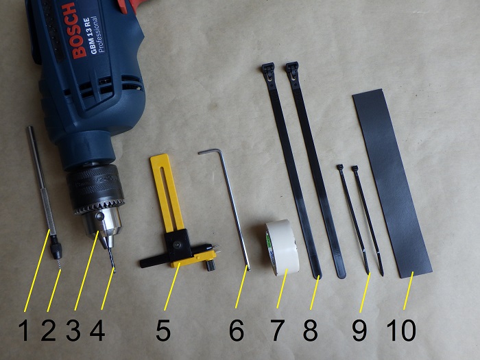
1. Goods to use
| No. | Products name | Manufacturer | Product number | Quantity | Amounts[Yen] | Purchase this time |
| ST1 | Dual-channel motorcycle dash cam | Mitsuba Sankowa | EDR-21A | 1 | 39,380 | |
| 1 | Pin vise | – | – | 1 | 890 | |
| 2 | Drill (1mm) | – | – | 1 | 129 | |
| 3 | Power drill | Bosch | GBM13RE | 1 | 22,880 | |
| 4 | Drill (2.5 and 5, 8mm) | – | – | 1 Each | 686 | |
| 5 | Compass cutter | OLPA | 57B | 1 | 505 | |
| ST6 | Well nut (M4, C-440) | KITAKO | 0900-678-05060 | 1 | 194 | ○ |
| ST7 | Screw (M4×12mm) | ESCO | EA949MS-412 | 1 | 213 | ○ |
| 6 | Long hex key (2.5mm) | KTC | HLD250-2.5 | 1 | 1,122 | |
| 7 | Vinyl tape (White) | – | – | 1 | 84 | |
| 8 | Cable ties (Repeatable) | ELPA | KBR-N200010(BK) | 2 | 312 | |
| 9 | Cable ties (2.5mm) | ELPA | KBF-N100100(BK) | 2 | 175 | |
| 10 | Sponge sheet (1.5mm) | INOAC | L32-1.550MT | 1 | (626) | |
| 67,196 | 407 |
2. Installing the Front Camera (STEP 1–25)
Parts to Be Installed
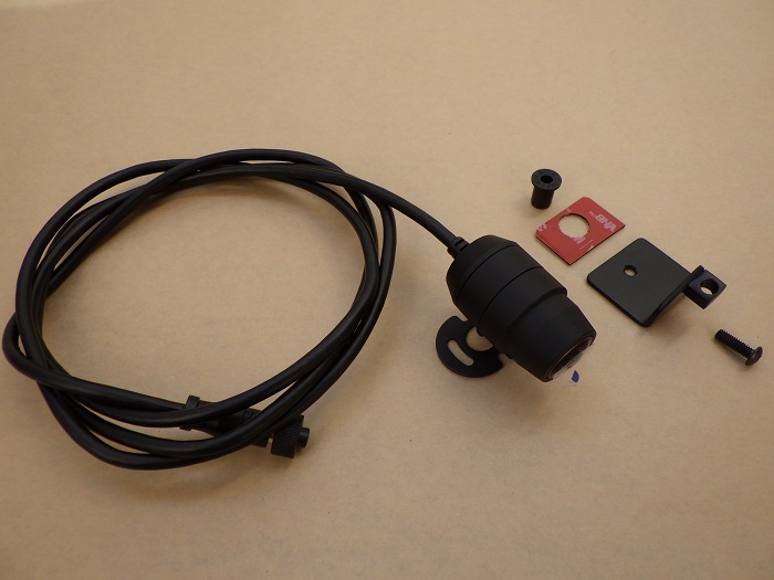
<Parts to Be Installed>
The following parts will be used (from left to right):
- Front camera
- Well nut for securing the front camera bracket
- Double-sided tape
- Front camera bracket
- Screw for securing the front camera bracket
For details on how the bracket was made, refer to “Motorcycle Dash Cam Installation 3 – Crafting the Camera Brackets”.
Removing the Front Cowl
To proceed with installation, I’ll:
- Drill a hole in the front cowl
- Bundle the wiring with existing cables
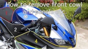
So first, I remove the front cowl.
For instructions, see “How to remove the front cowl and panels etc.”
Front Cowl with Headlight Removed
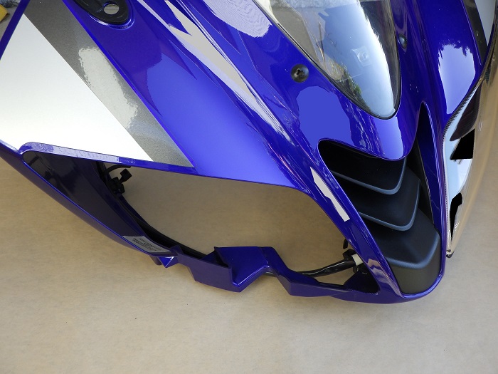
<Front Cowl with Headlight Removed>
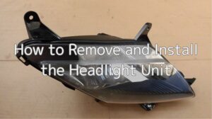
Since the drill point is close to the headlight, I also remove the right-side headlight.
(Instructions for removing the right headlight will be covered in a future post.)
Then, I temporarily mount the front cowl to the bike.
Drilling the Hole
Let’s prep for mounting the front camera.
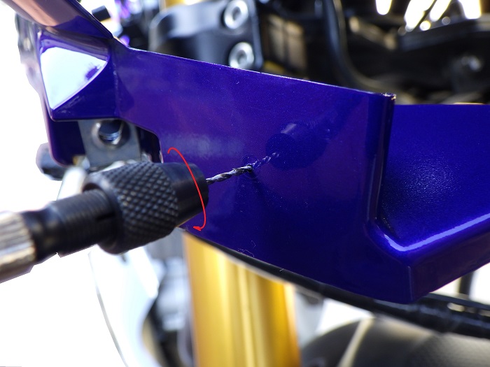
<Drilling the Hole>
Using a pin vise and drill, I make an 8mm hole in the lower right section of the front cowl.
To prevent cracking, I gradually enlarge the hole in the following order:
1mm (pin vise) → 2.5mm → 5mm → 8mm (power drill)
The cowl is thin, so without holding it firmly, the drill torque could easily crack it.
Also, I’m a bit worried the drilled area might break later from stress.
Modifying the Double-Sided Tape
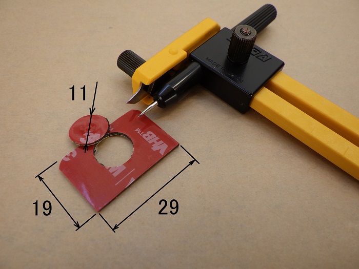
<Modifying the Double-Sided Tape>
Cut the included double-sided tape to 29×19mm and use a compass cutter to punch an 11mm hole.
Mounting the Front Camera Bracket 1
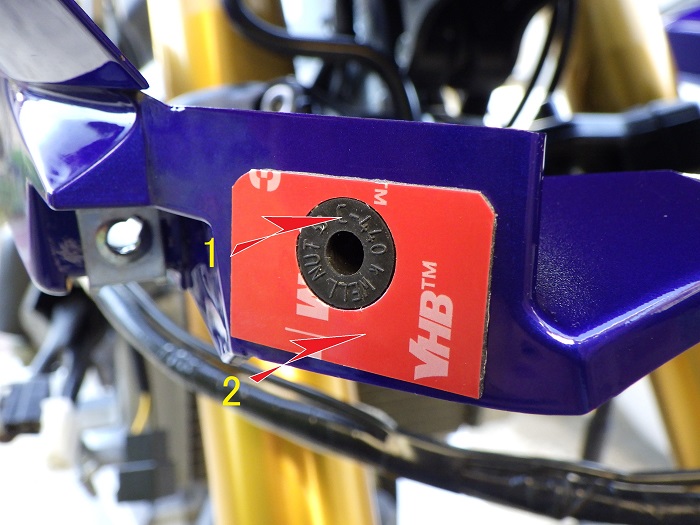
<Mounting the Front Camera Bracket 1>
- Insert the well nut into the hole in the front cowl
- Apply the double-sided tape around the well nut, avoiding direct contact
Mounting the Front Camera Bracket 2
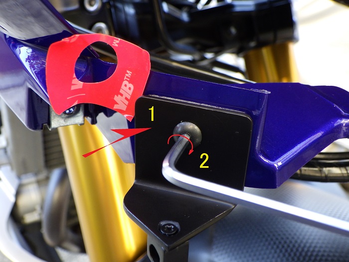
<Mounting the Front Camera Bracket 2>
- Peel off the tape backing and stick the bracket onto the front cowl
- Tighten the screw using a 2.5mm hex wrench
The tape alone might hold, but I added the screw for extra security and theft prevention.
Inside the Front Cowl
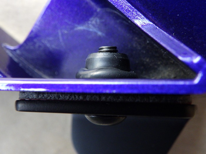
<Inside the Front Cowl>
Here’s how the well nut is secured.
No interference with other components, and it tightened up nicely.
Now I reinstall the right-side headlight.
Mounting the Front Camera
After removing the camera stay, I secure the front camera to the bracket base.
<Mounting the Front Camera>
Use a 2.5mm hex wrench to tighten the screw that secures both the camera and the stay.
Make sure the camera’s rotation mark (△) faces upward.
Vertical angle adjustments will be done later.
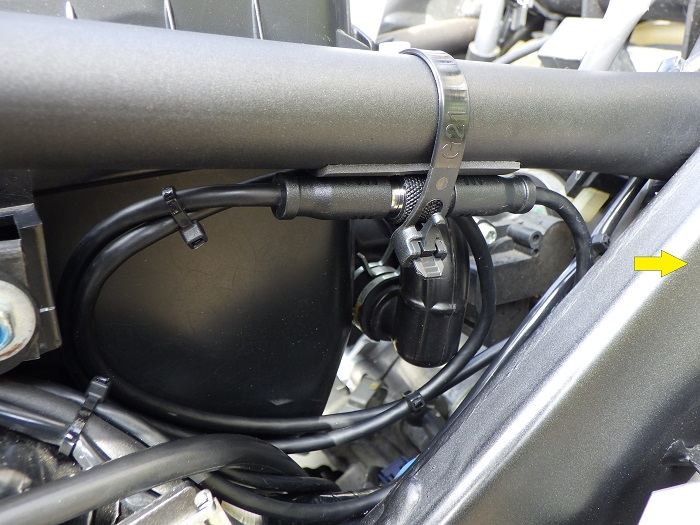
Securing the Wiring 1
No new cable mounts are used.
Instead, I bundle the front camera cable with the headlight wiring using two existing edge-clip cable ties.
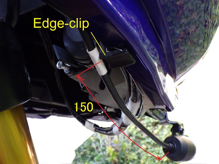
<Securing the Wiring 1>
To mark the cable tie location, I placed white tape 150mm from the front camera.
Securing the Wiring 2
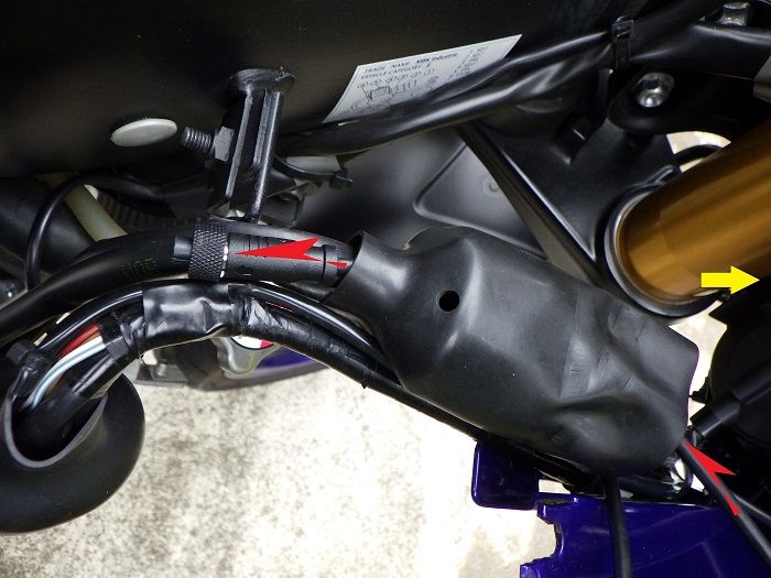
<Securing the Wiring 2>
Route the cable through the connector cover along with the headlight wiring, and pull it toward the bike frame.
Securing the Wiring 3
<Securing the Wiring 3>
Following the headlight wiring:
- Place the front camera cable, headlight wiring, and meter wiring in order onto the frame hooks
- Secure them at two points using reusable cable ties
I used reusable ties to avoid cutting them every time I remove the cowl.
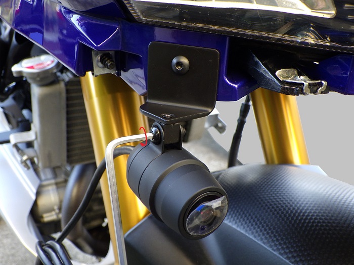
Installed Front Camera
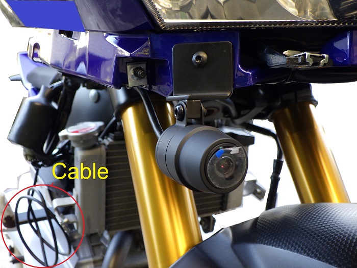
<Installed Front Camera>
Here’s how it looks when mounted.
From now on, I’ll need to be careful not to bump the camera when placing the cowl on the ground.
Also, like the rear, the cable is a bit long and slightly annoying.
Removing the Fuel Tank Cover and Tank
Next, to route wiring around the engine, I remove the fuel tank cover and the tank itself.
How to remove the fuel tank cover:
How to remove the fuel tank:
Fuel Tank Removed
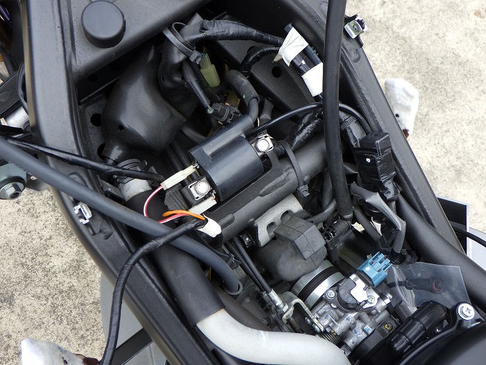
<Fuel Tank Removed>
With the tank out of the way, it’s easier to organize the wiring around the engine.
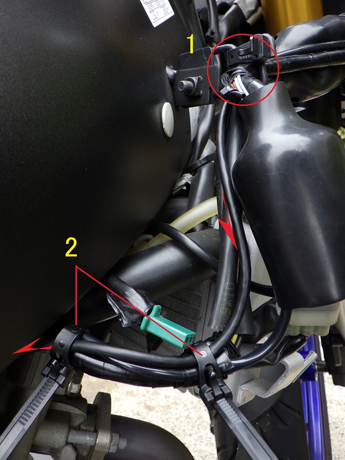
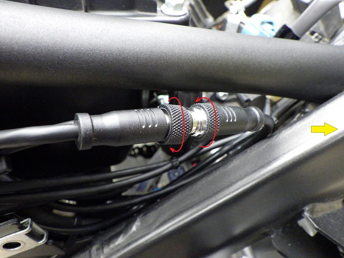
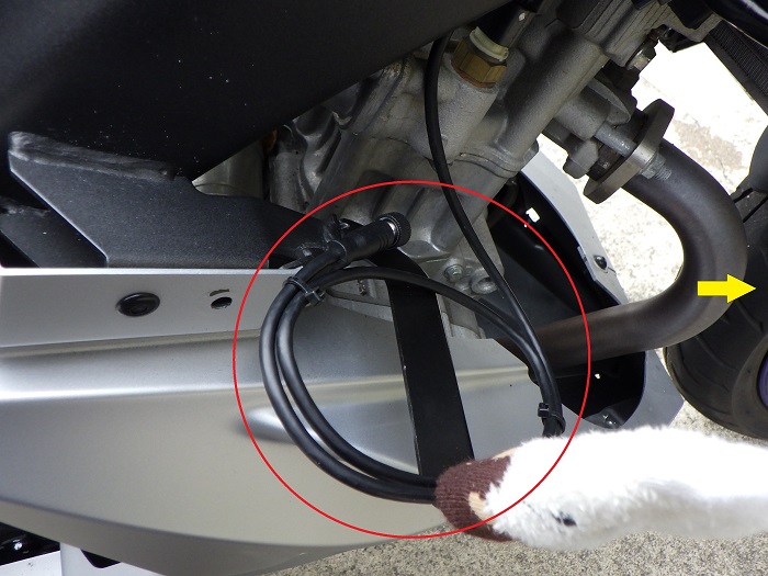
Intermediate Connector Position
Since the front cowl will be removed occasionally, the intermediate connector needs to be placed where it can be easily disconnected and reconnected.
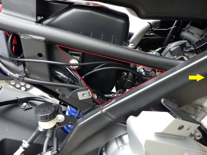
<Intermediate Connector Position>
Based on cable routing and length, the triangular section of the right frame (red box) looks ideal.
I’ll route the wiring to match this location.
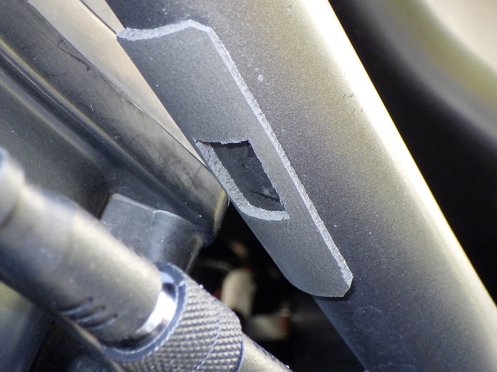
Securing the Wiring 4
<Securing the Wiring 4>
This photo shows the right frame from front to rear.
To allow cable routing without removing the tank, we guide the cable from the cable tie location in STEP 12 along the inside of the frame.
It almost touches the coolant hose, but since there’s minimal slack, I didn’t secure it further.
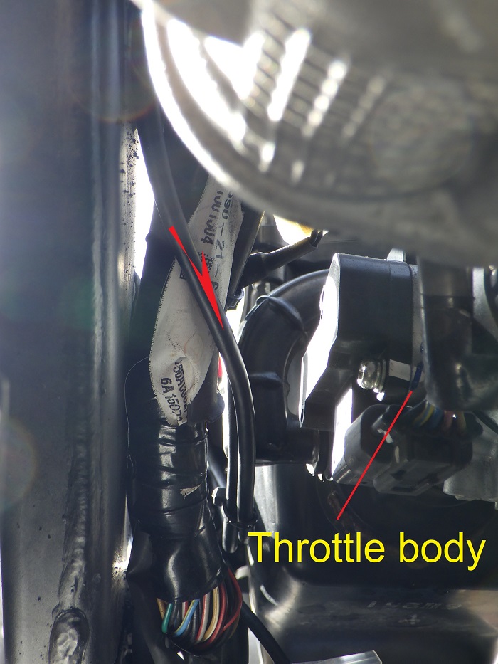
Securing the Wiring 5
Meanwhile, the cable from the main unit is also routed to the triangular frame section.
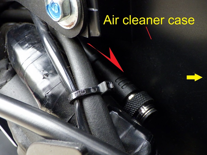
<Securing the Wiring 5>
The intermediate connector is routed along the side of the air cleaner case.
At first, I thought I’d need to remove the case, but I managed to squeeze it through.
Also routed the switch connector at the same time.
Securing the Wiring 6
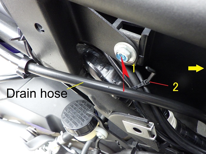
<Securing the Wiring 6>
- Lift the battery drain hose and route the front camera and switch cables from the main unit
- Bundle the vehicle wiring, theft alarm wiring, front camera, and switch cables with cable ties
Securing the Wiring 7
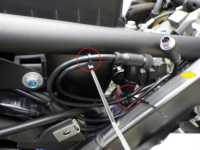
<Securing the Wiring 7>
Bundle the front camera cable at the triangular frame section and secure it with two cable ties.
Connecting the Intermediate Connector
<Connecting the Intermediate Connector>
Connect the intermediate connector.
The method is the same as for the power cable.
Modifying the Sponge Sheet
Use a sponge sheet to position and secure the intermediate connector.
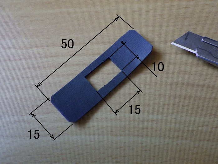
<Modifying the Sponge Sheet>
Cut the sponge sheet to 50×15mm and punch a 15×10mm hole using a cutter
Securing the Wiring 8
<Securing the Wiring 8>
Stick the sponge sheet to the underside of the frame.
Then secure the intermediate connector with a reusable cable tie.
Bundled Cables 1
<Bundled Cables 1>
Here’s how the cables are bundled.
This location offers good accessibility and makes installation/removal less of a hassle.
Bundled Cables 2
<Bundled Cables 2>
The bundled section can be pulled forward as-is.
So when reinstalling the front cowl, there’s no need to re-route the bundled wiring each time.
To be continued in “Motorcycle Dash Cam Installation Part 7 – Installing the Switch.”
3. Summary
Here’s a summary of the steps taken to install the front camera of the dashcam.
By fabricating a custom bracket, I gained more flexibility in choosing the mounting position for the front camera.
Bundling the camera cable with existing wiring—such as the headlight harness—helped reduce the “aftermarket” look.
Additionally, to improve serviceability, I designed the setup so the entire front cowl can be removed from the bike without disconnecting the camera.
- Removing the front cowl from the bike improves overall workability.
- When drilling into soft materials, a compass cutter is the ideal tool.
- I used a well nut to reduce vibration to the camera and prevent bracket theft.
On the other hand, double-sided tape alone may provide sufficient strength, and drilling into the cowl introduces a risk of cracking. - The camera cable was routed along the right side of the frame.
- The Intermediate connector was secured to the frame for easy disconnection during maintenance.