This is a continuation of “Motorcycle Dash Cam Installation 7 – Installing the Front Camera”.
In this eighth installment, I’ll be installing the switch.
The drive recorder used is the Mitsuba Sankowa / EDR-21A.
I’ll mount the custom-made bracket onto the left handle’s lever holder and secure the switch there.
From this article, you’ll learn:
- How to install the switch and bracket
- How to route the switch wiring
- Additional tasks required for installation
| Date | 16th December 2023 |
| Subjects | Tuning, Customizing |
| Shop or DIY | DIY |
| Difficulty | |
| Working hours | 3 |
| Costs [Yen] | 0 (Use what I have) |
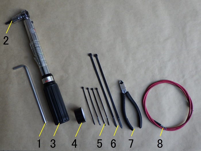
1. Goods to use
| No. | Product name | Manufacturer | Product number | Quantity | Amounts[Yen] |
| ST1 | Dual-channel motorcycle dash cam | Mitsuba Sankowa | EDR-21A | 1 | 39,380 |
| 1 | Long hex key (5mm) | KTC | HLD250-5 | 1 | 1,419 |
| 2 | Hexagon bit socket (5mm) | KTC | BT3-05S | 1 | 1,045 |
| 3 | Torque wrench (Small) | KTC | CMP0252 | 1 | (44,990) |
| 4 | Insulating tape | OHM | DE1910K | 1 | (84) |
| 5 | Cable ties (2.5mm) | ELPA | KBF-N100100(BK) | 4 | 175 |
| 6 | Cable ties (4.8mm) | ELPA | KBZ-N200100 | 2 | 769 |
| 7 | Miniature nippers | HOZAN | N-35 | 1 | 3,465 |
| 8 | Cable puller | STRAIGHT | 19-457 | 1 | (1,380) |
| 92,707 |
2. Installing the Switch (STEP 1–18)
Parts to Be Installed

<Parts to Be Installed>
The following parts will be used.
From left to right:
- Switch
- Switch bracket
For details on how the bracket was made, refer to the maintenance record:
Motorcycle Dash Cam Installation Part 4 – Crafting the Switch Bracket.
Switch Bracket Installation 1

<Switch Bracket Installation 1>
Using a 5mm hex wrench, remove the two bolts securing the left handle’s lever holder.
To prevent the lever angle from shifting, mark the seam of the lever holder beforehand.
This angle seems to affect wrist circulation—changing it can noticeably impact fatigue during clutch operation.
Switch Bracket Installation 2

<Switch Bracket Installation 2>
Insert the switch bracket and tighten the two bolts using a torque wrench with a 5mm hex socket. (9 N·m)
Installed Switch Bracket

<Installed Switch Bracket>
Here’s how it looks once secured.
Although it’s made from 1.2mm thick aluminum, the small surface area provides sufficient strength.
Cable Fixing Points
Before attaching the switch, I routed the cable along the bike’s wiring and identified where to secure it with cable ties.

<Cable Fixing Points>
Depending on the distance from the switch, I applied black electrical tape at the following points:
- 80mm
- 235mm
- 390mm
I usually use white tape, but since these areas are visible, I opted for black to keep it discreet.
Switch Installation

<Switch Installation>
- Peel off the backing of the double-sided tape on the switch and stick it onto the bracket.
- Route the cable along the wiring near the left handle and secure it at the 80mm mark with a cable tie.
Care was taken to ensure the cable doesn’t touch the top bridge or front fork.
Cable Fixing 1
Continue routing the cable along the existing wiring.

<Cable Fixing 1>
Cut the cable ties securing the bike’s wiring, add the switch cable, and re-tighten with new ties.
- Between the front fork and stem (Loosely tightened due to shared use with clutch cable)
- Along the frame (Shared with radiator mount)
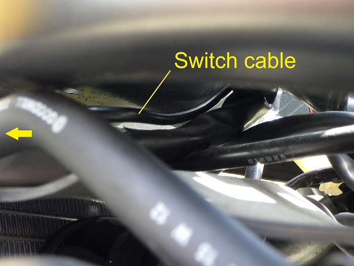
Cable Routing 1
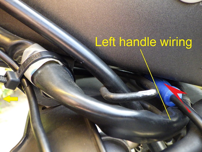
<Cable Routing 1>
Pass the switch connector through the location shown in the photo.
However, when trying to route it along the left handle wiring into the frame, it got stuck midway and wouldn’t go through.
Cable Routing 2
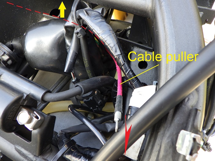
<Cable Routing 2>
Using a cable puller, I was able to route it smoothly.
Cable Routed Inside Frame
<Cable Routed Inside Frame>
Here’s how the cable looks after being routed inside the frame.
Cable Bundling Strategy
Now let’s consider how to bundle the cable inside the frame.
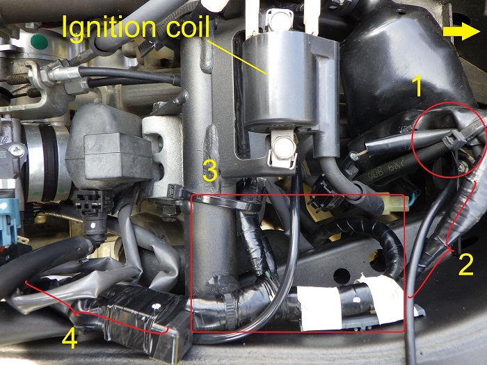
<Cable Bundling Strategy>
- I’d prefer to keep some distance from the ignition coil cable
- I’d also like to avoid the front camera connection area
So, I bundled it as follows:
- Use the cable tie at the right side of the photo to group the wiring
- Route along the right side of the frame
- Coil the cable within the red frame area
- Connect to the intermediate connector along the right side of the frame
Burglar Alarm Wiring
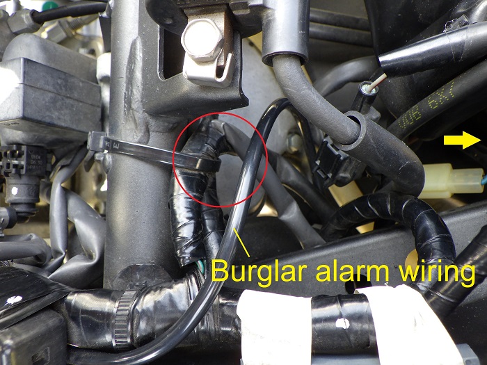
<Burglar Alarm Wiring>
By the way, the burglar alarm wiring I previously routed without removing the fuel tank turned out surprisingly neat.
I had considered re-routing it during this process, but it seems unnecessary.
However, I decided to bundle it together at the red circle area.
Cable Fixing 2
Now let’s bundle the cables.

<Cable Fixing 2>
- Bundle the wiring
- Bundle the burglar alarm wiring
- Coil any excess cable and secure it with three cable ties
Cable Fixing 3
Route the cable further toward the rear.

<Cable Fixing 3>
Follow the burglar alarm wiring.
Intermediate Connector Connection
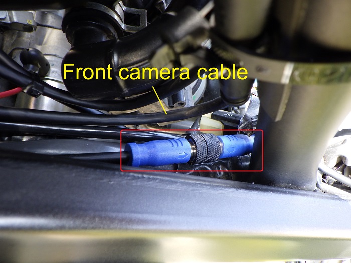
<Intermediate Connector Connection>
Connect the intermediate connector at the midsection of the right frame.
To avoid interference when removing the front camera cable, I positioned it as far to the right (toward the bottom of the photo) as possible.
Bundled Cable

<Bundled Cable>
Here’s the final bundled cable.
With this, cable routing is complete.
I managed to fit everything inside the frame.
Switch Condition

<Switch Condition>
Meanwhile, here’s how the switch looks.
Unfortunately, the mounting position was slightly off, and the double-sided tape ended up higher than expected.
Even though I made a custom bracket, misplacing the tape defeats the purpose…
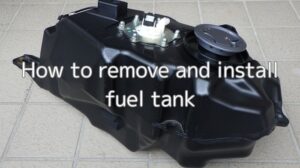
Fuel Tank & Cover Installation
With this, all drive recorder-related components have been installed.
Now I’ll reinstall the fuel tank and the cowl/panel parts.
How to install the fuel tank:
How to install the fuel tank cover:

Next up: Motorcycle Dash Cam Installation Part 9 – Operation Check & Camera Position Adjustment
3. Summary
Here’s a summary of the switch installation process.
By fabricating a bracket, I was able to position the switch above the lever holder.
Compared to the camera installation, this task wasn’t particularly difficult.
- Leave slack in shared cable ties for cables that move with steering
- Use a cable puller for tight routing spots
- Since the switch is rarely removed, the intermediate connector was tucked inside the frame