Instead of simply swapping a halogen bulb for a store-bought LED bulb, this guide explains how to assemble an LED bulb yourself.
The R125 uses two position bulbs, and the bulb type is T10.
Benefits of assembling your own LED bulb:
- You can choose LEDs to match the color of your headlight bulb.
- You can build a bulb cheaply using parts from established LED manufacturers.
- Even if one LED burns out, you can replace or repair it individually.
From this article, you’ll learn:
- How to assemble an LED position bulb.
| Date | 24th September 2022 |
| Subjects | Tuning, Customizing |
| Shop or DIY | DIY |
| Difficulty | |
| Working hours | 1 |
| Costs [Yen] | 1,350 |
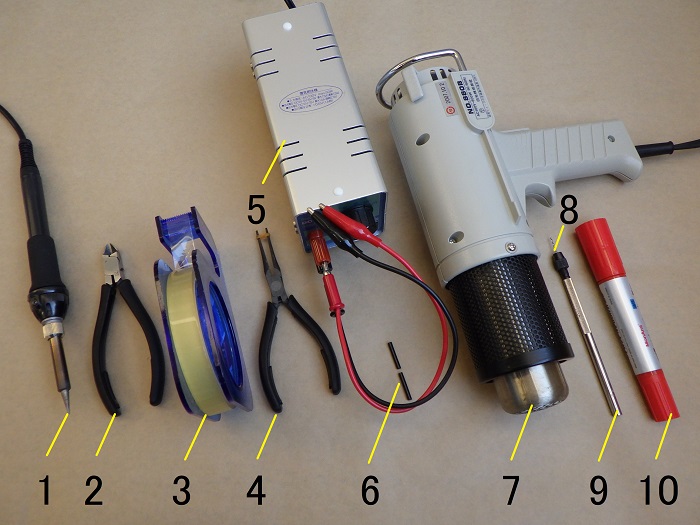
1. Goods to use
| No. | Products name | Manufacurer | Products number | Quantity | Amounts[Yen] | Purchase this time |
| ST1 | LED Position Bulb Kit | LED Paradise | 6577 | 1 | 670 | ○ |
| 1 | Soldering controller | TAIYO ELECTRIC | PX-601AS | 1 | 17,600 | |
| 2 | Cutting pliers | HOZAN | N-35 | 1 | 3,465 | |
| ST6 | Bullet-shaped LED(φ5) | NICHIA | NSDL570GS-K1 | 6 | 540 | ○ |
| 3 | Cellophane tape | – | – | 1 | 153 | |
| 4 | Pliers | HOZAN | P-37 | 1 | 3,179 | |
| 5 | Regulated power supply | SANHAYATO | DK-811 | 1 | (21,978) | |
| 6 | Heat shrinkable tube (φ2) | – | – | 1 | 74 | |
| 7 | Heating gun | HAKKO | 880B | 1 | (7,260) | |
| 8 | Drill(0.7mm) | – | – | 1 | 956 | |
| 9 | Pin vise | – | – | 1 | 890 | |
| 10 | Red marker | – | – | 1 | 109 | |
| – | Shipping charge | – | – | 1 | 140 | ○ |
| 57,014 | 1,350 |
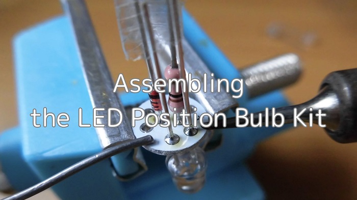
2. Assembling the LED Position Bulb Kit (STEP 1–18)
Position Bulb Kit
<Position Bulb Kit>
I’ll use the position bulb kit from LED Paradise.
However, to match the color of the low-beam LED headlight (6000K), I prepared a warm-white LED instead of the kit’s included LED.
Soldering the Resistor
Let’s get started with the work.
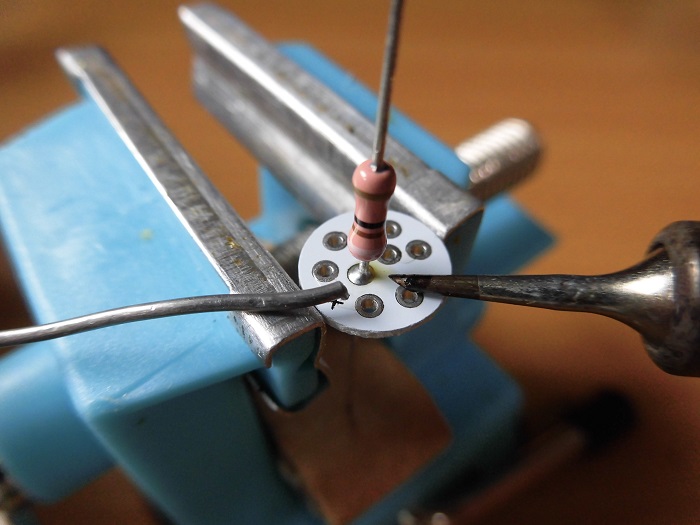
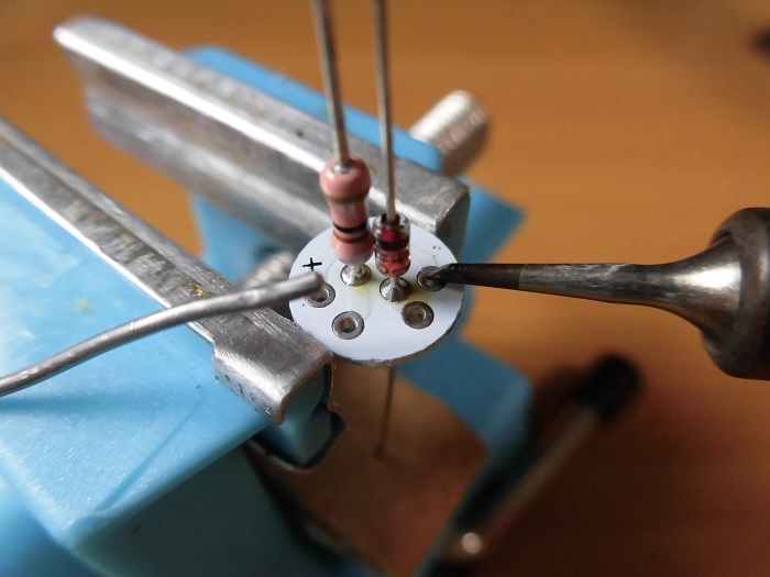
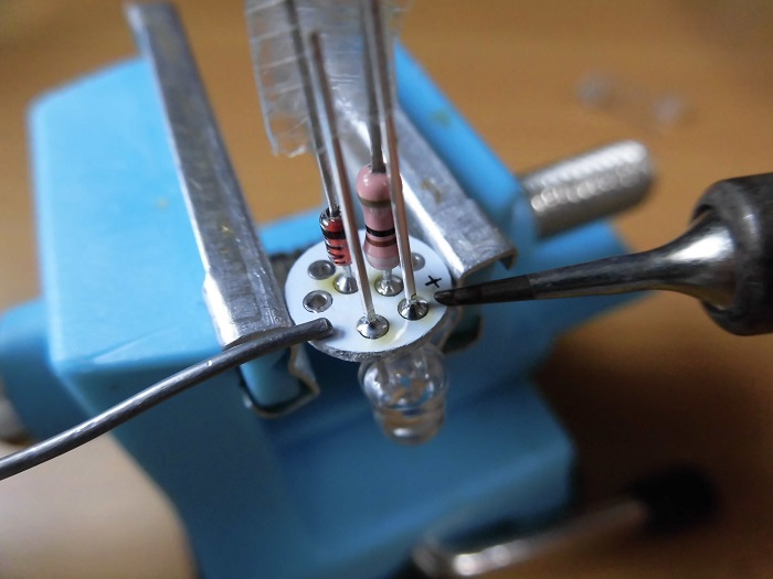
<Resistor Soldering>
Solder the resistor to the positive side.
If you don’t mount it close enough to the circuit board, it will hit the wedge base.
Cutting Lead Wire 1
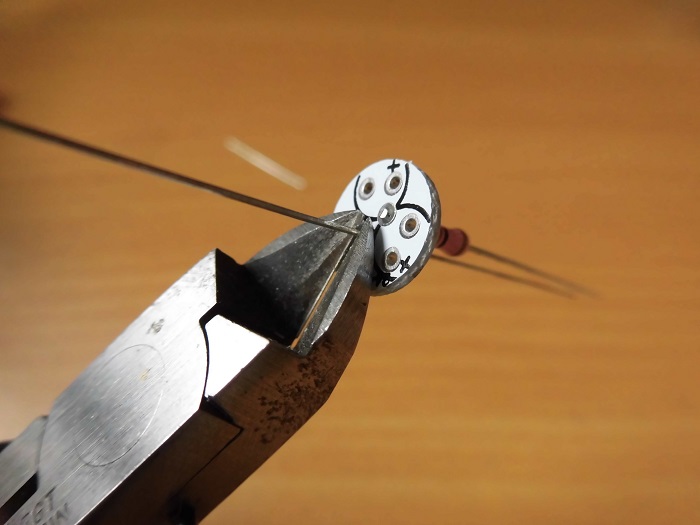
<Cutting Lead Wire 1>
Cut off the excess lead wire at the root.
Soldering the Diode
<Diode Soldering>
Solder the diode to the negative side.
Be careful—the diode has polarity.
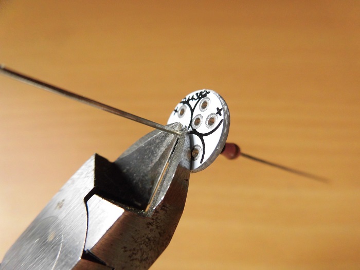
Cutting Lead Wire 2
<Cutting Lead Wire 2>
Cut off the excess lead wire at the root.
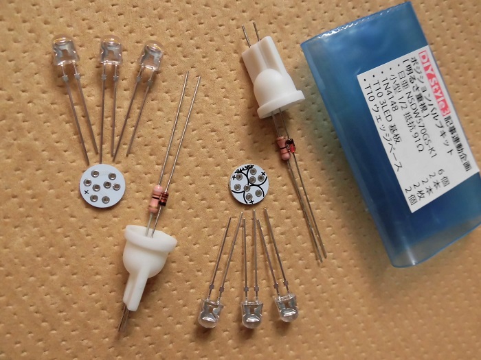
LED Comparison
As mentioned in STEP 1, I prepared a warm-white LED.
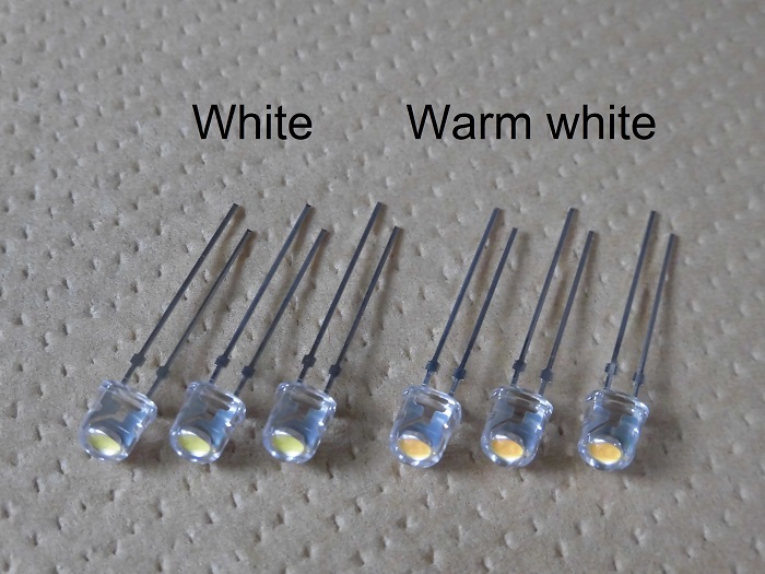
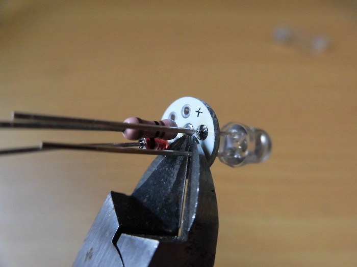
<LED Comparison>
Left: White — Nichia NSDW570GS-K1 (included in kit)
Right: Warm-white — Nichia NSDL570GS-K1
Since the forward voltage and current are the same, you can swap them without changing the kit’s configuration.
Installing the LED
Alright, let’s mount the LED onto the circuit board.
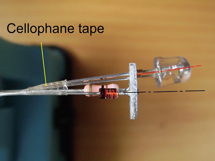
<LED Installation>
Insert the longer lead (anode) into the positive hole.
Fix the leads to the resistor and diode with cellophane tape.
When three LEDs are lined up, the outer diameter is larger than the board, so they won’t sit straight.
To keep them tilted outward, I used cellophane tape.
Soldering the LED
<LED Soldering>
Solder the LEDs in place.
Cutting Lead Wire 3
<Cutting Lead Wire 3>
After soldering the LEDs, cut off the excess lead wire at the root.
Then, install the other two LEDs in the same way.
Bending the LEDs
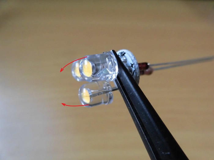
<LED Bending>
Bend the outward-facing LEDs inward using pliers or your fingers.
Adjust gradually while checking the balance of all three.
Lighting Test
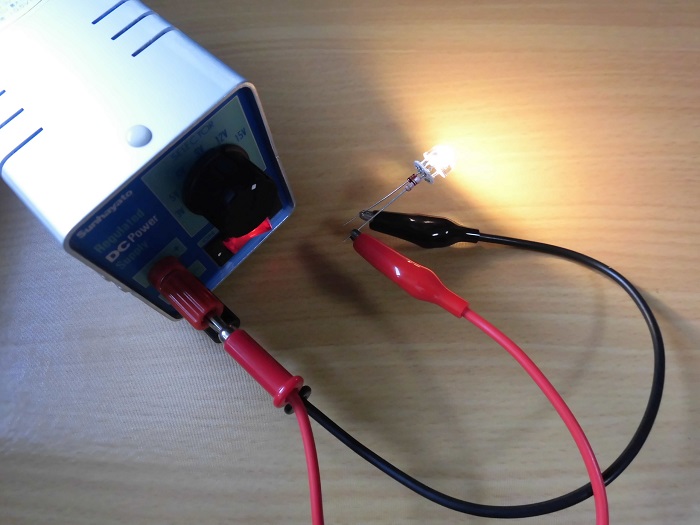
<Lighting Test>
Use a regulated power supply to power the LED bulb and confirm it lights up.
Connect positive to the resistor side, negative to the diode side.
Thanks to the diode, the bulb won’t break even if polarity is reversed.
Heat Shrink
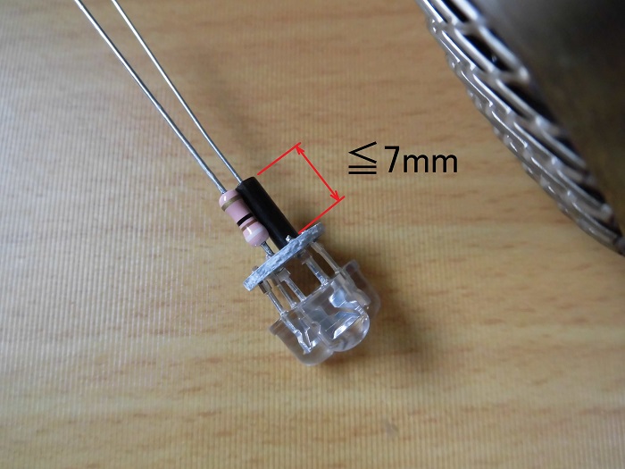
<Heat Shrink>
To prevent short circuits, attach heat-shrink tubing to the diode side.
Make sure the tubing is shorter than about 7 mm, otherwise it will hit the inside of the wedge base.
Drilling the Wedge Base
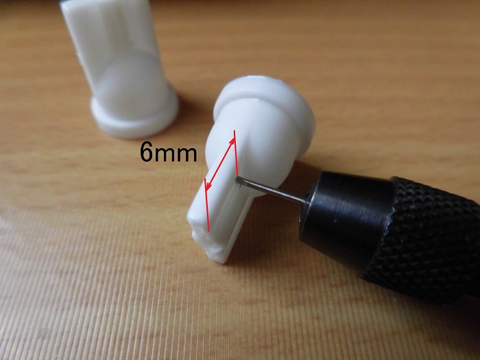
<Drilling the Wedge Base>
Drill holes in the wedge base to secure the lead wires.
Using a 0.7 mm drill bit on a pin vise, I drilled holes about 6 mm from the edge of the wedge base.
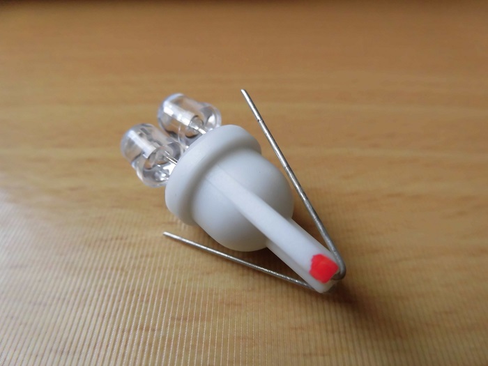
Marking the Positive Side
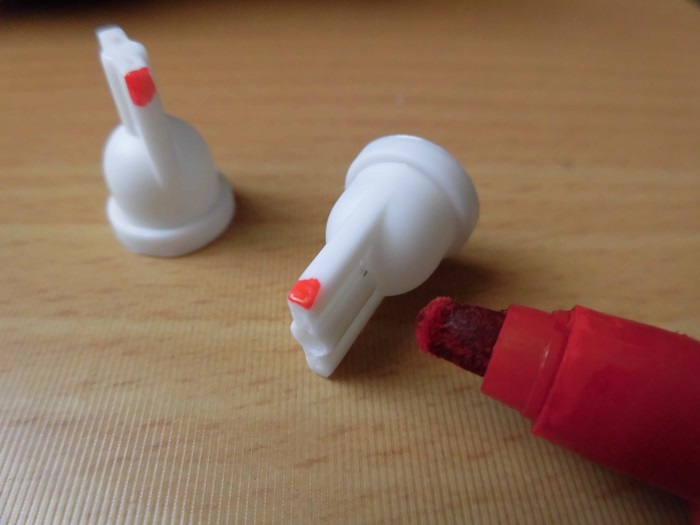
<Marking the Positive Side>
To identify the positive side, I marked the wedge base with a red line.
If you don’t know which side of the vehicle wiring is positive or negative, you’ll just have to install it and check.
Attaching the Wedge Base 1
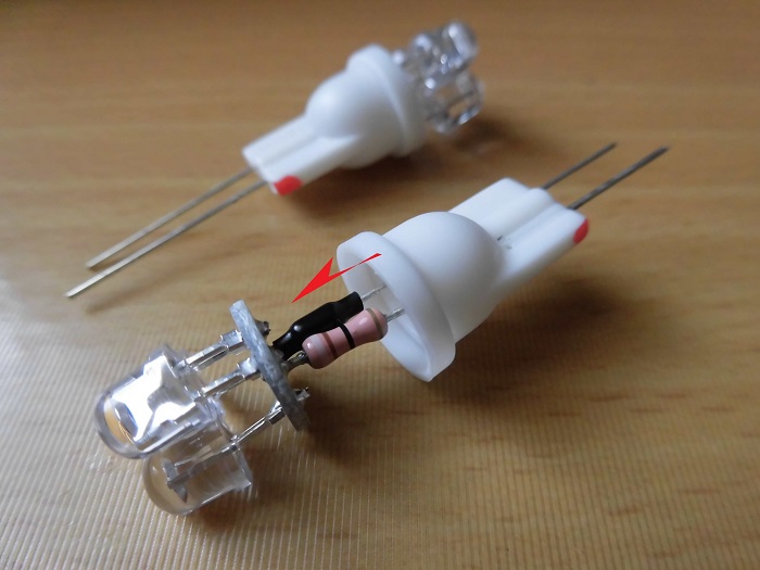
<Attaching the Wedge Base 1>
Pass the resistor and diode leads through the holes in the wedge base.
Insert the resistor on the side marked with the red line.
Attaching the Wedge Base 2
<Attaching the Wedge Base 2>
Fold back the lead wires sticking out of the wedge base, cut them leaving a little extra length.
Attaching the Wedge Base 3
<Attaching the Wedge Base 3>
Then, bend the ends of the lead wires with pliers and insert them into the holes drilled in STEP 13.
The circuit board and wedge base are not fixed together in any special way.
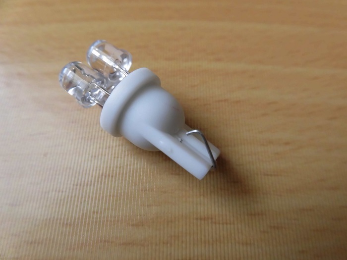
Assembled LED Bulb
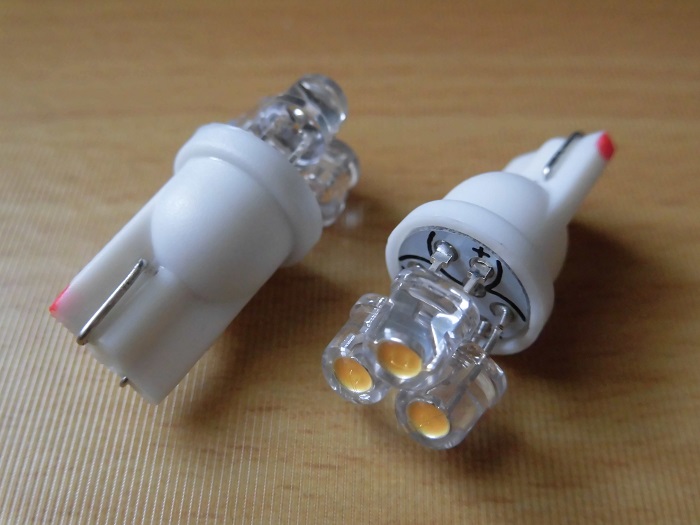
<Assembled LED Bulb>
Here’s the finished product.
3. Summary
I’ve gone through how to assemble an LED position bulb kit.
This work is closer to electronics than motorcycle maintenance but soldering and wiring follow the same principles as electronic device assembly.
- Ready-made assembly kits are available
- You can choose your LEDs
- Diodes and LEDs have polarity, so pay attention to orientation
- Mark the positive side of the LED bulb with red