I have always wanted to protect my moto from mischief and theft, so I was interested in a security device.
I looked on the Internet and learned that there was a theft alarm (Protec/CS-550M) that could be retrofitted, and I thought this would be a good idea, so I purchased it.
Before starting the work, I did some preliminary research on the installation of a burglar alarm, but could not find any detailed information.
It’s obvious when you think about it, and if I were to write down specifics, the anti-theft protection of that bike would lose its meaning, right?
So, I think below and will summarize the installation process in four parts.
- I would be very happy if it would be helpful for those who are considering installing a theft alarm.
- The device/wiring is hidden in the cowl/panel, so it should be fine.
- I doubt many people will ever see this article.
In this first installment, we will examine the installation process.
From this article, you can learn the following.
- Designation and possible locations for installation of a burglar alarm
- Example of installing positions of burglar alarm components
| Date | 15th November 2021 |
| Subjects | Tuning, Customizing |
| Shop or DIY | DIY |
| Difficulty | |
| Working hours | 3 |
| Costs [Yen] | 12,758 |
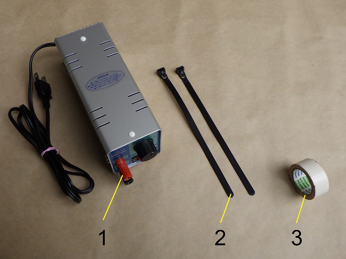
1. Goods to use
| No. | Product name | Manufacturer | Product number | Quantity | Amounts[Yen] | Purchase this time |
| ST1 | Burglar alarm | PROTEC | CS-550M | 1 | 12,758 | ○ |
| 1 | Regulated power supply | SANHAYATO | DK-811 | 1 | (21,978) | |
| 2 | Cable ties (Repeatable) | ELPA | KBR-N200010(BK) | 2 | 312 | |
| 3 | Vinyl tape White | – | – | 1 | 84 | |
| 35,132 | 12,758 |
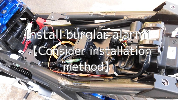
2. Install burglar alarm1【Consider installation method】(STEP 1-16)
Confirmation of operation
First, make sure the alarm works.
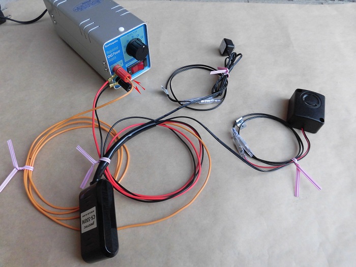
<Confirmation of operation>
A regulated power supply is used to apply 12V to the alarm.
The orange wire is the wire that senses when the ignition is on or off. So, I activated it by attaching and detaching it to the positive power supply.
The sound of the siren indicating that the alarm is set was quite loud and surprising.
Study of installing position of main unit 1
Next, consider where to install the burglar alarm body.
The specifications for installation in the instruction manual are as follows.
- Have an upper and lower level.
- Place it where it will not be exposed to water (it is not waterproof).
- Place it so that the wires face down (to prevent water from getting inside).
- Do not place it near a siren (the vibration of the siren will cause an endless loop).
Locations that may satisfy the above are as follows.
- Between tank cover and tank
- Between the seat/seat cowl and the mudguard
I also wanted to install it on the frame, not on the box or mudguard, which I personally have the opportunity to remove.
In fact, taking these factors into account, I think the number of places it can be installed is quite limited.
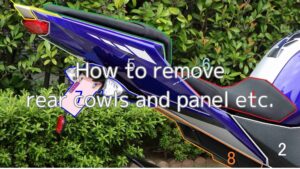
Remove rear cowls and panel etc.
Now, let’s find a position to install it in the implementation.
First, remove the rear cowl, panel, etc., and then, for ease of work, remove the box as well.
(For details, please refer to the maintenance record “How to remove rear cowls amd panel etc.”)
Study of installing position of main unit 2
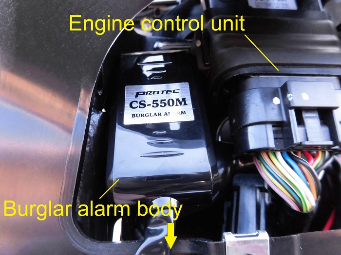
<Study of installing position of main unit 2>
Idea 1: Next to the engine control unit.
This was my main choice, but the main unit hit the frame. (Too bad!).
What should we do?
Study of installing position of main unit 3
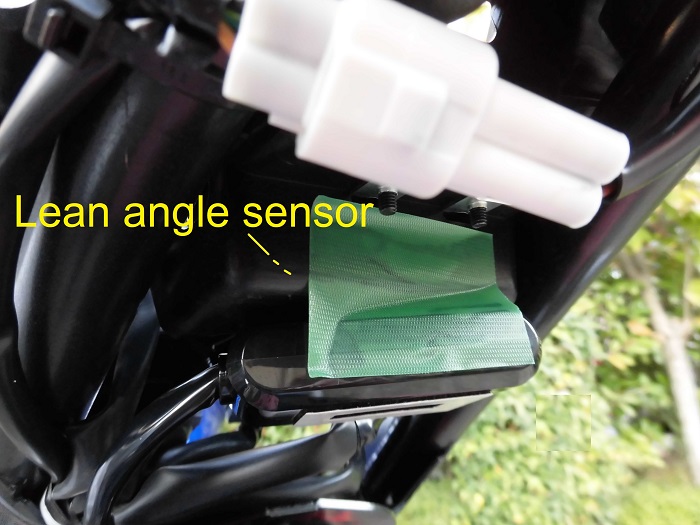
<Study of installing position of main unit 3>
Idea 2: underside of the lean angle sensor
Next, although not in the frame, we considered the underside of the lean angle sensor (the underside of the box).
This position is completely invisible from the outside.
You can’t even see it when the seat or tandem seat is removed, so I would almost forget that I had installed it too.
Unfortunately, however, the rear cowl slightly hit it.
However, it was a tough spot because it looks like some water might get in…
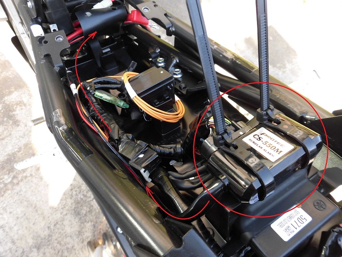
Study of installing position of main unit 4
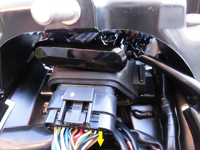
<Study of installing position of main unit 4>
Idea 3: Above the engine control unit
I’ve already decided here.
It will take some work, but we will make a bracket and install it on the top side of the control unit.
I don’t feel good about being so close to the control unit, but I guess it’s okay since the theft alarm works when the engine is stopped.
Fabricated bracket
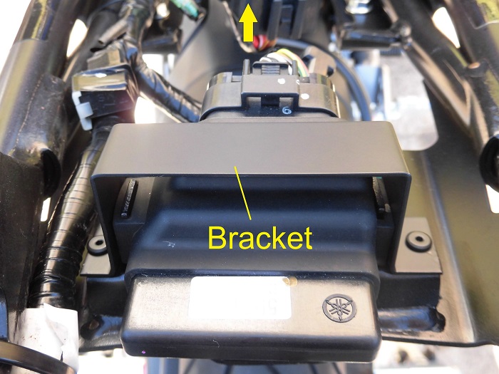
<Fabricated bracket>
Out of the blue, I fabricated a bracket using an aluminum plate like this.
The bracket is placed across the engine control unit and secured with two low-head bolts.
(For details, please refer to the next maintenance record, “Make bracket for the burglar alarm”)
Wiring diagram
Next, consider the wiring routing and the mounting position of the siren and LED indicator lamp.
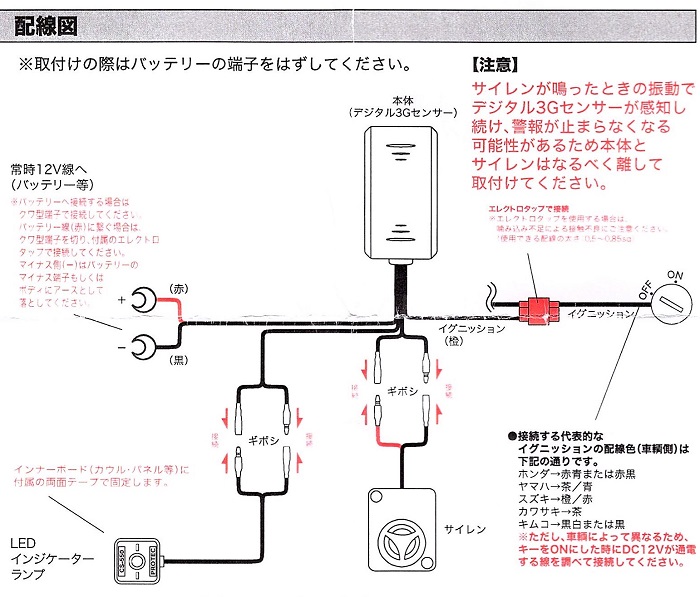
Wiring diagram (Extract from instruction manual)
The wiring will be the following four wires.
- LED indicator lamp
- Permanent 12V (power supply) positive and negative
- Ignition
- Siren
Wiring connections
For STEP 8 1 and 2, connect to the following
1. Ignition
Connect to wiring from ignition power supply
2. Permanent 12V
Pull the wires to the back side of the battery.
(See Maintenance Record, “Extract wiring from ignition power supply” for details.)

Burglar alarm temporarily installed
Now, temporarily install the main body of the burglar alarm to the moto body and determine the wiring.
<Burglar alarm temporarily installed>
Temporarily install the main body of the burglar alarm to the bracket with a cable tie and pass it along the main harness on the left side of the moto body to the back side of the battery.
Branch of wiring 1
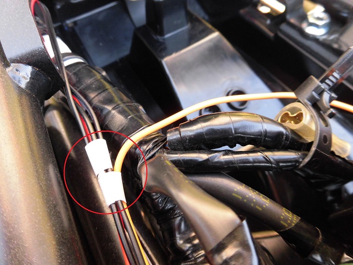
<Branch of wiring 1>
Branch the Ignition wiring in STEP9, 2.
As identification, paste white tape before and after the branching so that the position and wiring of the branching can be identified.
Branch of wiring 2
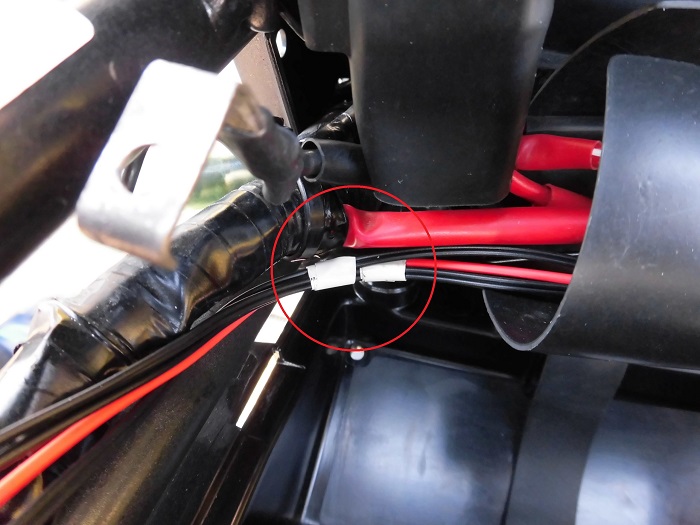
<Branch of wiring 2>
Next, branch the siren wiring in STEP 9, 3.
Harness protector
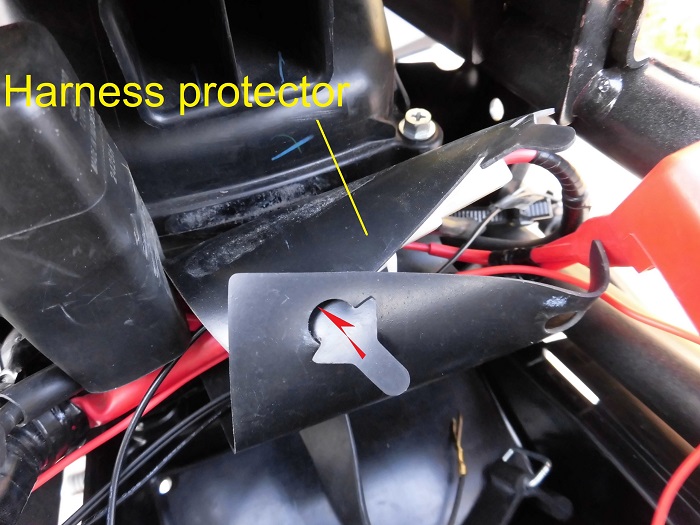
<Harness protector>
Open the harness protector where the power supply-related wiring is gathered by removing the arrow-shaped maple.
Place the wiring for STEP 9, 1. Permanent 12V and 4. LED indicator, in this harness protector.
The specific wiring arrangement will be explained at the time of installation.
Remove fuel tank cover
First, remove the fuel tank cover.
(For details, see the maintenance record “How to remove fuel tank cover.”)

Installation position of siren
Now, consider the installation position of the siren.
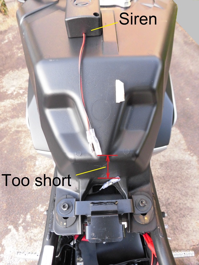
<Installation position of siren>
After much consideration, I decided to install it on top of the fuel tank.
The wiring is not long enough here, so we need to add about 150 mm to the wiring.
I started to look for a good place under the seat, but the siren is surprisingly large and I could not find a satisfactory place.
Installation position of LED indicator lamp
Finally, consider the position of the LED indicator lamp.
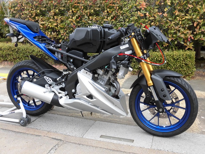
<Installation position of LED indicator lamp>
I decided to install it on the right side of the meter, as I thought it would be a good position to be able to see it when trying to move the bike.
The wiring length is not long enough, so the following steps are required.
- Front cowl side: add 180mm
- From the back side of the battery to the front cowl: Extend the wiring by 960mm.
3. Summary
In this issue, I have been thinking about the installation location of burglar alarm.
Surprisingly, there are some restrictions, and when I considered the actual installation position, I realized that it is very limited.
Recent super sports bikes have very little storage space under the seat and the rear cowl is compact. So, it may be difficult to install an ETC, etc.
On the other hand, if you can modify the wiring by yourself, you can freely decide the installation position.
Enjoy choosing the best location and installation under the limited conditions.
- The best location for installing the burglar alarm unit seems to be between the tank cover and the tank, seat/seat cowl and mudguard.
- If the siren is installed above the tank, the wiring length will be insufficient.
- Wiring length will be insufficient if the indicator lamp is placed along the wiring of the meter unit.