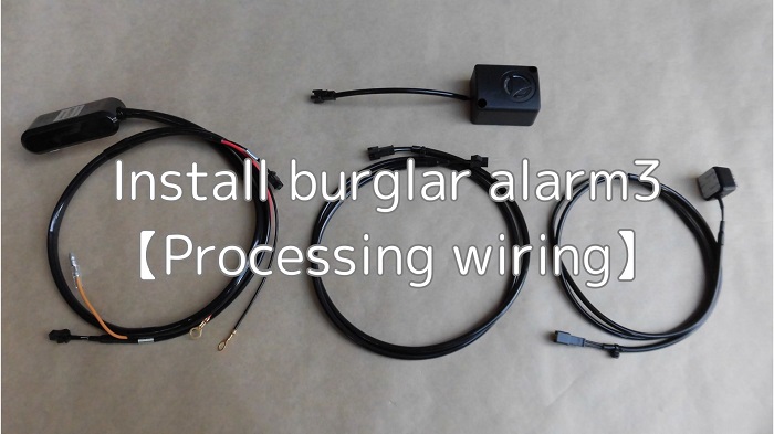
In this third installment, I will modify the wiring for the burglar alarm.
The wiring for each wire is processed to the length determined in the maintenance record “Install burglar Alarms 1【Consider installation method】”.
Although it takes some time to modify the wiring, the wiring can be arranged to fit the moto body, so it can be finished without feeling as if it has been retrofitted.
From this article, you can learn the following.
- How to process wiring for burglar alarm body, siren, and LED indicator.
- Making wiring extension.
- Connections using general-purpose connectors without bullet terminal.
| Date | 19th March 2022 |
| Subjects | Tuning, Customizing |
| Shop or DIY | DIY |
| Difficulty | |
| Working hours | 6 |
| Costs [Yen] | 909 |
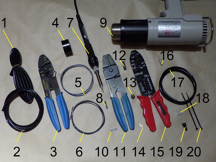
1. Goods to use
| No. | Product name | Manufacturer | Product number | Quantity | Amounts[Yen] | Purchase this time |
| 1 | Harness tube (φ6, 1m) | – | – | 1 | 165 | |
| 2 | Harness tube (φ4, 1m) | – | – | 2 | 154 | ○ |
| ST2 | Burglar alarm | PORTEC | CS-550M | 1 | 13,409 | |
| 3 | Crimping tool | HOZAN | P-704 | 1 | 5,148 | |
| 4 | Insulating tape | OHM | DE1910K | 1 | (84) | |
| 5 | Wire (1m, black & white stripe) | Sumitomo wiring | AVSSB03f-BKWH | 1 | 160 | |
| 6 | Wire (1m, black) | Sumitomo wiring | AVSSB03f-BK | 1 | 160 | |
| 7 | Soldering controller | TAIYO ELECTRIC | PX-601AS | 1 | 17,600 | |
| 8 | Heat shrinkable tube (φ2) | – | – | 1 | 74 | |
| 9 | Heating gun | HAKKO | 880B | 1 | (7,260) | |
| 10 | SM connector female terminals | JST | SHF-001T-0.8BS | 6 | 78 | |
| 11 | Crimping tool | HOZAN | P-706 | 1 | 6,743 | |
| 12 | Heat shrinkable tube (φ4.8, 10cm) | Sumitomo wiring | WPSHTU-48BK | 1 | 242 | ○ |
| 13 | SM connector female housing | JST | SMP-02V-BC | 3 | 165 | |
| 14 | Ring terminals for M5, short type | – | – | 2 | 78 | ○ |
| 15 | Crimping tool | STRAIGHT | 12-679 | 1 | 630 | |
| 16 | Bullet terminal and sleeve | – | – | 1 | 153 | |
| 17 | Harness tube (φ3, 1m) | – | – | 1 | 55 | ○ |
| 18 | SM connector male terminals | JST | SYM-001T-P0.6 | 6 | 78 | |
| 19 | SM connector male housing | JST | SMR-02V-B | 3 | 132 | |
| 20 | Cable tie (2.5mm) | ELPA | KBF-N100100(BK) | 2 | 175 | |
| – | Shipping charge | – | – | 1 | 380 | ○ |
| 53,123 | 909 |
2. Install burglar alarm3【Processing wiring】(STEP1-29)
Prepare harness tube
First, prepare harness tubing according to the position and diameter of the branch.
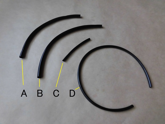
<Prepare harness tube>
It is perfectly fine without it, but it will look like a genuine part after installation because the wiring is organized.
From the top,
A…φ6 170mm
B…φ6 190mm
C…φ4 70mm
D…φ4 310mm
Install these parts in order.
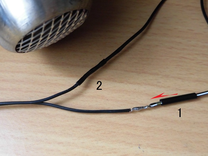
Cut terminal
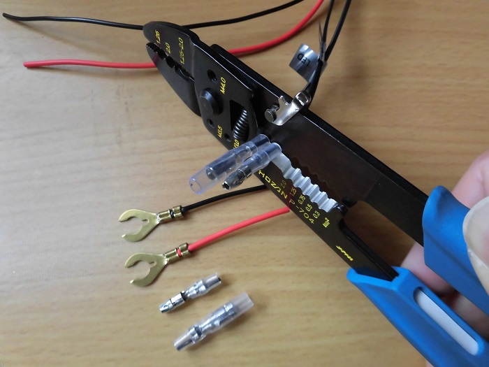
<Cut terminal>
If there are any bullet or spade terminals attached, they cannot be passed through the harness tube. So, they must be cut off.
It would be a waste to cut the terminals crimped by the manufacturer, but it is unavoidable in order to make the wiring fit the moto body.
In any case, I was planning to cut them when adjusting the length. So, I am prepared for that.
By the way, I cut the stag terminal at about 45 mm from the crimp, but later I noticed that the wiring on the positive side was shorter.
I should have cut both at about 30 mm.
Pass through harness tube
<Pass through harness tube>
Thread the harness tube from STEP 1, A, through the wires.
Be careful not to twist the wiring inside the tube as much as possible.
Fix harness tube
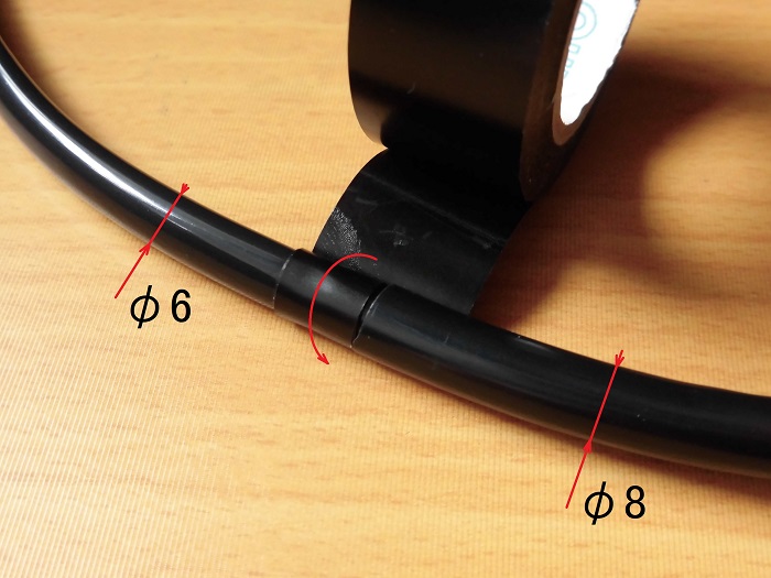
<Fix harness tube>
Since the diameter of the tube (φ8) attached to the main body of the alarm and the tube (φ6) that was threaded through later were different, wrapping the insulation tape around the tube would cause wrinkles.
Therefore, we wrapped two rolls of tape cut in half around the φ6 tube and then pasted the tape over the joint.
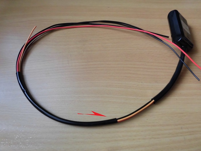
Branch processing 1
Next, make the first branch.
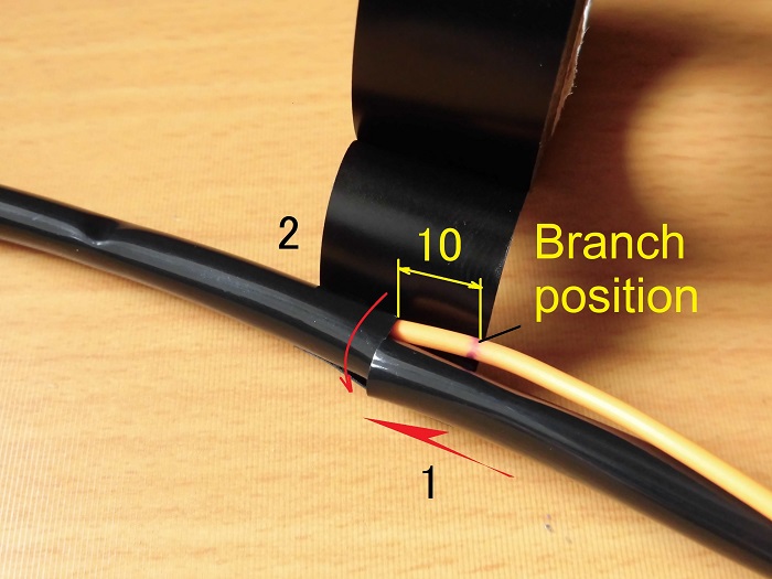
<Branch processing 1>
- Run the harness tube from STEP 1, B through the other wires except for the orange wire (ignition wiring).
- Wrap insulation tape around the joints of the harness tube.
The branch will be located about 10mm away from the alarm body from the alignment of the harness tube.
Process wiring on siren side 1
Now, I will process the wiring on the siren side.
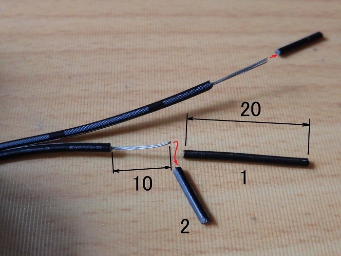
<Process wiring on siren side 1>
- Cut about 20 mm off one side of the wiring so that the wires do not overlap.
- Peel off about 10 mm of the wiring sheath.
Process wiring on siren side 2
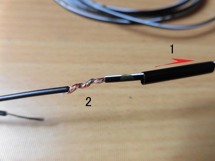
<Process wiring on siren side 2>
- Pass the heat-shrinkable tubing through it.
- Connect the siren wiring and the additional wiring (0.3sq)
Solder wiring on the siren side
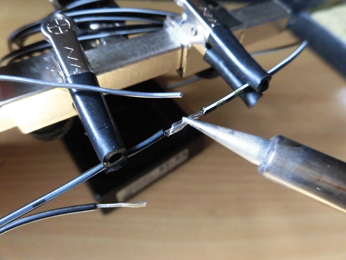
<Solder wiring on the siren side>
Solder the yoked area.
Heat shrink wiring on siren side 1
<Heat shrink wiring on siren side 1>
- Cover the soldered area with heat shrink tube.
- Shrink the heat shrink tube with a heat gun.
Process wiring on siren side 3
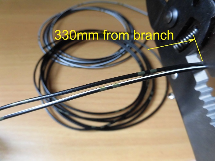
<Process wiring on siren side 3>
Cut the wiring at 330 mm from the branch, taking into account the shortfall of 150 mm that was investigated in STEP 15 of “Install burglar alarm1【Consider installation method】”.
Branch processing 2
Next, make the second branch.
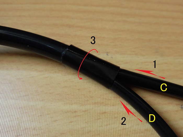
<Branch processing 2>
- Run the harness tube from STEP 1, C, through the siren wires.
- Pass the harness tube from STEP 1, D through the other wires.
- Wrap insulation tape around the joints of the harness tubes.
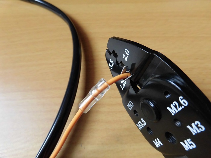
Crimp terminals on siren side
Next, crimp the terminals to the wires on the siren side.
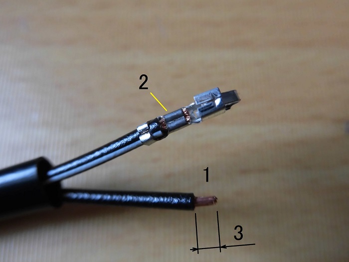
<Crimp terminals on siren side>
- Peel off about 3mm of the wiring sheath.
- Crimp the terminals with crimping tool.
Heat shrink wiring on siren side 2
<Heat shrink wiring on siren side 2>
Cover the end of the harness tube with heat-shrinkable tube and heat-shrink.
Install connector on siren side
<Install connector on siren side>
Insert the terminal into the connector.
In fact, once I applied too much heat and melted the harness tube. So, I had to rebuild it.
Furthermore, when I peeled off the heat-shrink tube, I damaged the wiring sheath, so I covered it with insulation tape.
It’s a complete disaster. What am I doing?
Terminal crimp failure
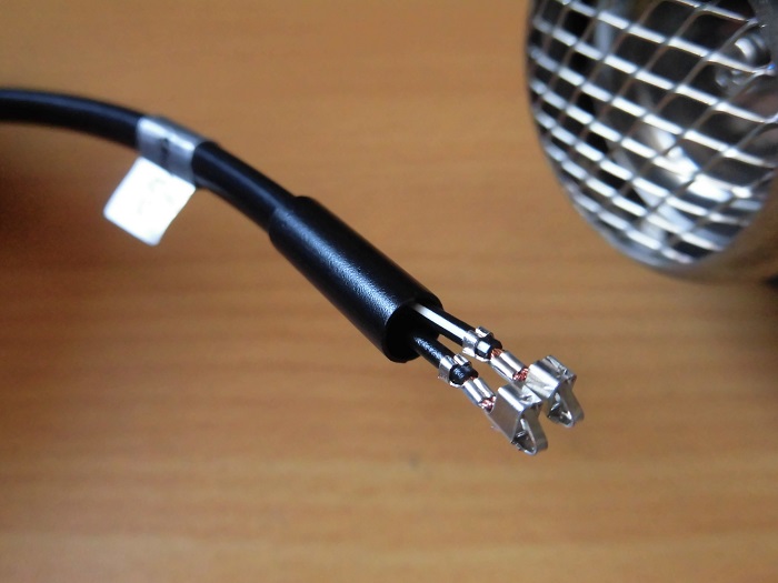
Then, I processed the wiring on the LED indicator light side in the same way as the wiring on the siren side.
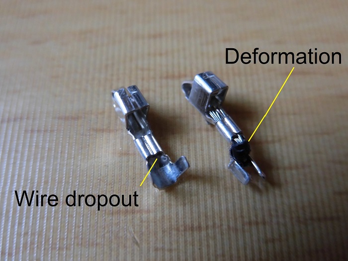
<Terminal crimp failure>
I thought I could crimp the terminals as easily as on the siren side, but I failed twice.
Left: disconnected wiring after crimping.
The core wire of the LED indicator is only about 0.2sq and it is thin.
So, after the second attempt, I folded the core wire and crimped it.
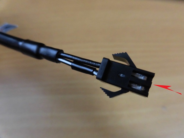
Right: When I crimped the wiring sheath, the terminal was violently deformed.
I don’t know what happened.
I crimped in the dark with my presbyopic eyes, so I didn’t notice that the terminals were tilted.
I guess it is difficult to crimp thin wires…
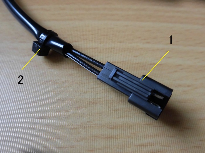
Wiring on LED indicator lamp side with connector
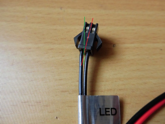
<Wiring on LED indicator lamp side with connector>
Furthermore, because the terminal was crimped out of position, there was a difference in the length of the left and right wires, causing the connector to tilt.
As I did not have the energy to crimp it back on, I left it as it was.
Crimp terminals on permanent 12V wiring
Next, process the permanent 12V wiring.
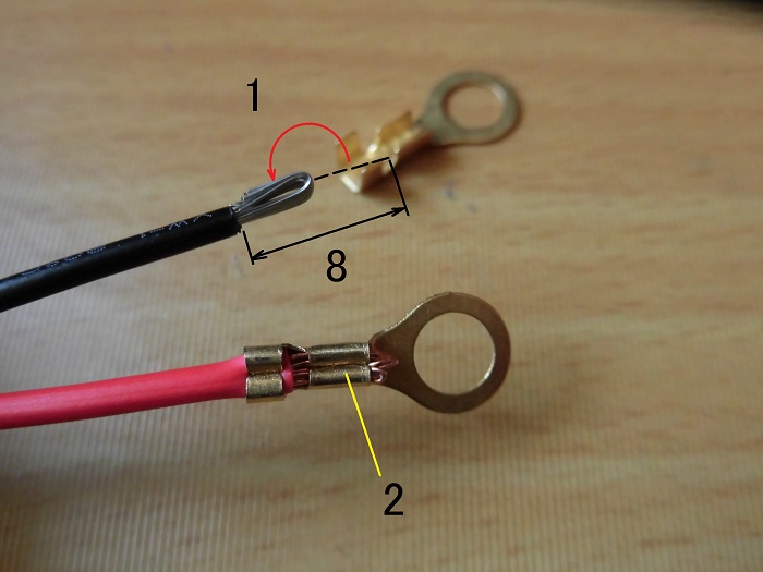
<Crimp terminals on permanent 12V wiring>
- Peel off about 8mm of the wiring sheath, and fold back the core wire (using the lessons learned in STEP 15).
- Crimp the terminals with crimping tool.
Crimp terminals on ignition wiring
In addition, process the wiring for the ignition.
First, cut the wiring at approximately 70 mm from the branch.
This is in accordance with the wiring for the ignition power supply made in the maintenance record “Extract wiring from ignition power supply”.

<Crimp terminals on ignition wiring>
After passing the sleeve through, peel off about 8 mm of the wiring sheath and fold back the core wire.
Then, using crimping tool, crimp the crimp terminals.
Processed wiring of alarm body
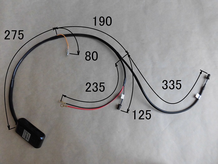
<Processed wiring of alarm body>
Finished like this.
One-off harness for R125 (5D7W) is completed.
- Since the harness tube is black and does not look like it was retrofitted, it should be highly effective in preventing theft
- The harness tube is black, so it looks chic!
*It is better to have about 250mm of 12V wiring at all times!
Process wiring of siren
Now, the next step is to process the wiring for the siren.
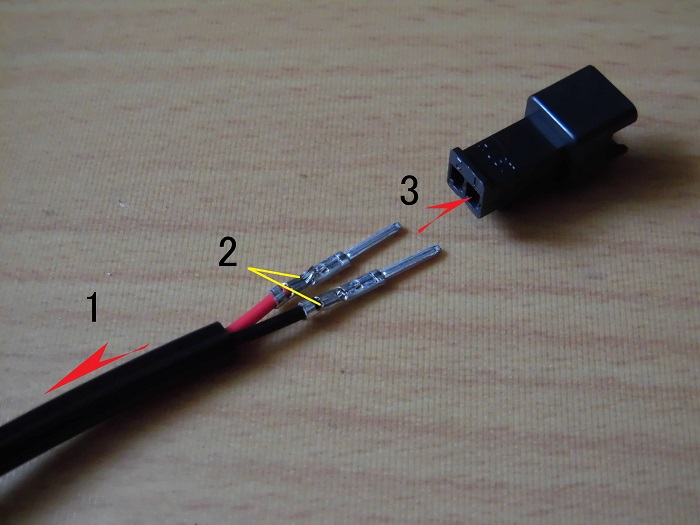
<Process wiring of siren>
- Pass through a harness tube (φ3) cut to 100 mm
- Crimp the terminals
- Insert terminals into the connector.
Comparison of siren wiring before and after processing
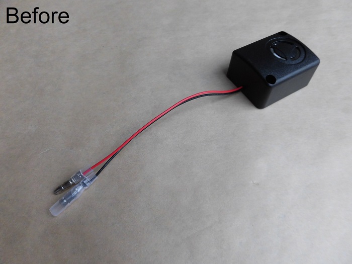
<Before processing>
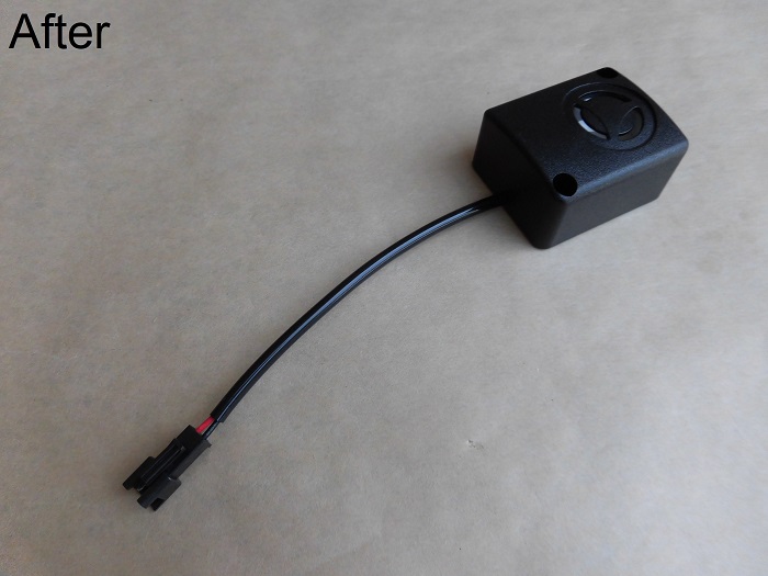
<After processing>
This one was worked simply, with no length adjustment.
Process wiring of LED indicator lamp 1
Now, the next step is to process the wiring for the LED indicator lamp.
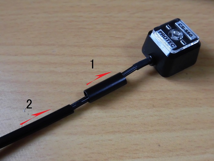
<Process wiring of LED indicator lamp 1>
- Pass through heat-shrinkable tube
- Pass through a harness tube (φ3) cut to 635 mm
Pass through wiring
In fact, I had a very hard time getting the wire through because the tube was so long.
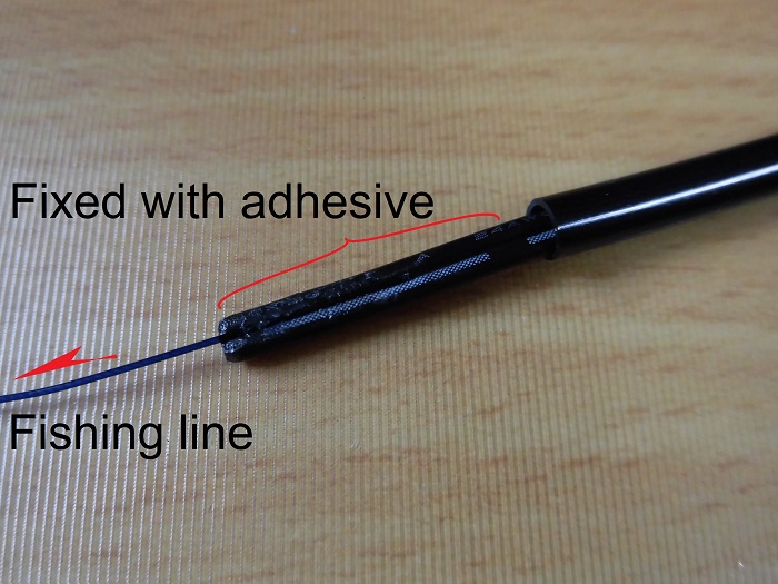
<Pass through wiring>
I placed a fishing line in the recess between the two cores and poured in instant adhesive to harden it.
I then pulled the line through the tube beforehand and managed to get the wire through.
Heat shrink wiring of LED indicator lamp
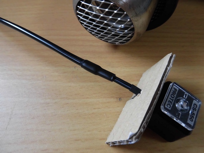
<Heat shrink wiring of LED indicator lamp>
Cover the end of the harness tube with heat-shrinkable tube and heat-shrink.
The indicator is covered with cardboard to prevent it from melting under heat.
Process wiring of LED indicator lamp 2
<Process wiring of LED indicator lamp 2>
The indicator wiring is not long enough. So, I added wiring (0.3sq).
- Solder the wires and cover with heat shrink tube
- Insert the harness tube (φ4) cut to 205mm
Then, wrap insulation tape around the joints.
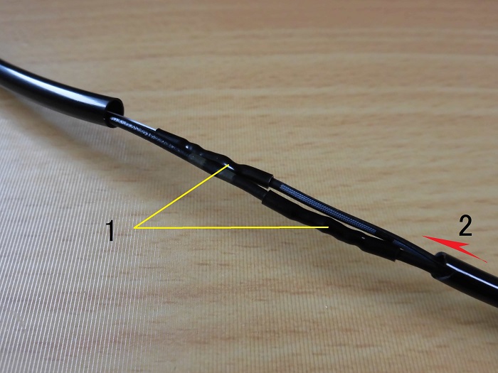
Process wiring of LED indicator lamp 3
<Process wiring of LED indicator lamp 3>
- Crimp the terminals and insert them into connector.
- Secure the ends of the harness tube with cable tie.
Comparison of LED indicator lamp wiring before and after processing
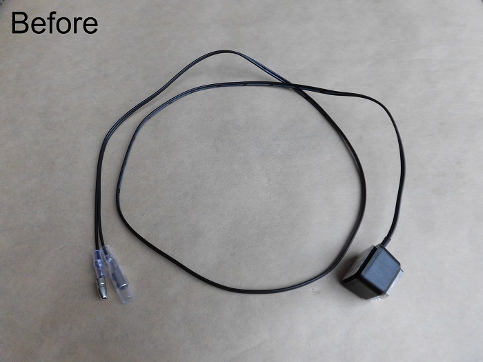
<Before processing>
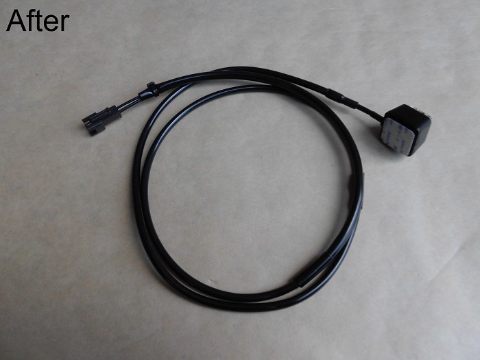
<After processing>
It is a little disappointing that the harness tube is thicker only in the area where the wiring was added, but it can’t be helped.
Extension wiring
Finally, make the wiring (extension wiring) between the alarm itself and the LED indicator lamp.
This part is completely self-made.
As the process is almost the same as for other wiring, I will skip this part.
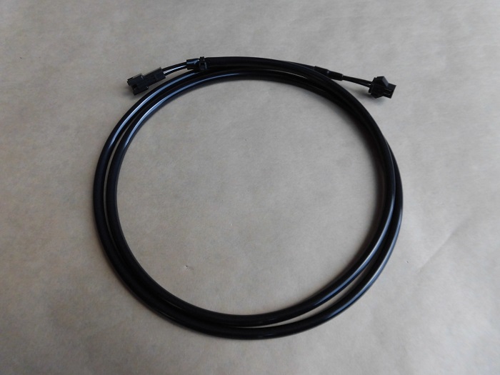
<Extension wiring>
Wiring (0.3sq) with total length of 960mm
Harness tube (φ4) with length of 900mm
Processed wirings
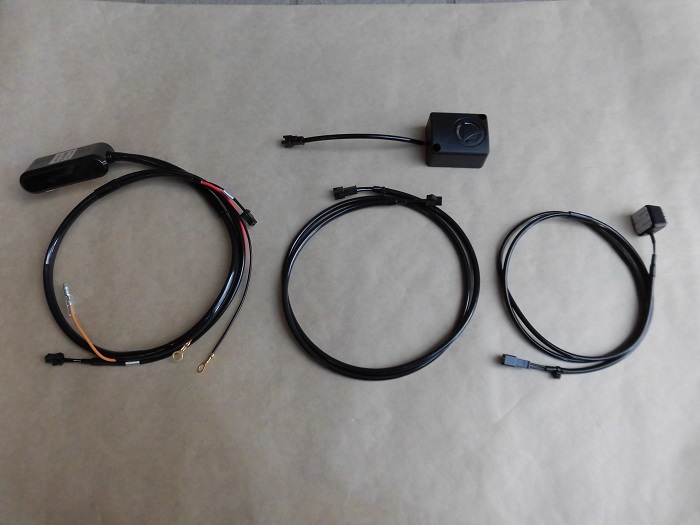
<Processed wirings>
It came together like this.
From left to right:
Alarm body wiring…57g
Siren wiring…28g
Extension wiring…18g
LED indicator lamp wiring…16g
Total: 119g
3. Summary
In this issue, I have summarized the wiring process for the burglar alarm body, siren, LED indicator, and other wiring.
For the wiring connections, I used general-purpose 2-pole connectors. So, the wiring can be disconnected smoothly when removing the tank and front cowl.
It took some time and effort, but I was able to create my own exclusive wiring.
- Excessive heat will melt the harness tube.
- When crimping terminal on thin wire (0.3sq), it is recommended to fold back the core wire.
- When threading wires into the harness tube, glue a fishing line into the recesses between the wires and pull it through.
- Cover with cardboard if you do not want it to melt during heat shrinking