Now that I’ve prepared the necessary brackets, it’s time to mount the drive recorder onto the bike.
The model I’m using is the Mitsuba Sankowa EDR-21A.
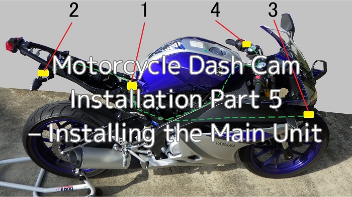
The mounting positions of each component and the wiring layout, as determined in the maintenance record “Motorcycle Dash Cam Installation Part 1 – Planning the Setup” are as follows.
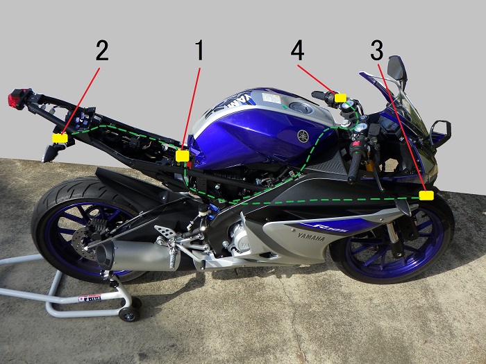
<Wiring Layout>
- Drive recorder main unit: Above the battery
- Rear camera: Right side of the license plate bracket
- Front camera: Lower right of the front cowl
- Switch: Mounted on the left handlebar lever holder
*I’ll cover the location of the intermediate connector during the installation steps.
In this fifth installment of the series, I’ll be mounting the main unit of the drive recorder.
From this article, you’ll learn:
- How to install the drive recorder’s main unit
- How to route the wiring from the unit
- What additional tasks are needed for installation
| Date | 1st December 2023 |
| Subjects | Tuning, Customizing |
| Shop or DIY | DIY |
| Difficulty | |
| Working hours | 6 |
| Costs [Yen] | 0 |
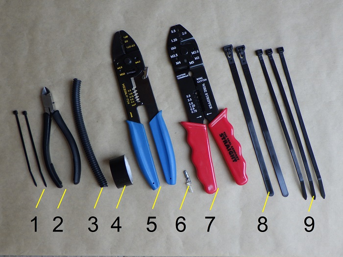
1. Goods to use
| No. | Name | Manufacturer | Product number | Quantity | Amounts[Yen] |
| ST3 | Dual-channel motorcycle dash cam | Mitsuba Sankowa | EDR-21A | 1 | 39,380 |
| 1 | Cable ties (2.5mm) | ELPA | KBF-N100100(BK) | 2 | 175 |
| 2 | Miniature nippers | HOZAN | N-35 | 1 | 3,465 |
| 3 | Corrugated Tube (φ7) | ELPA | SR-070H | 1 | (516) |
| 4 | Insulating tape | OHM | DE1910K | 1 | (84) |
| 5 | Crimping tool | HOZAN | P-704 | 1 | 5,148 |
| 6 | Bullet terminal and sleeve | – | – | 1 | 153 |
| 7 | Crimping tool | STRAIGHT | 12-679 | 1 | 630 |
| 8 | Cable ties (Repeatable) | ELPA | KBR-N200010(BK) | 2 | 312 |
| 9 | Cable ties (4.8mm) | ELPA | KBZ-N200100 | 3 | 769 |
| 50,632 |
2. Installing the Main Unit (STEP 1–23)
Fabricated Brackets
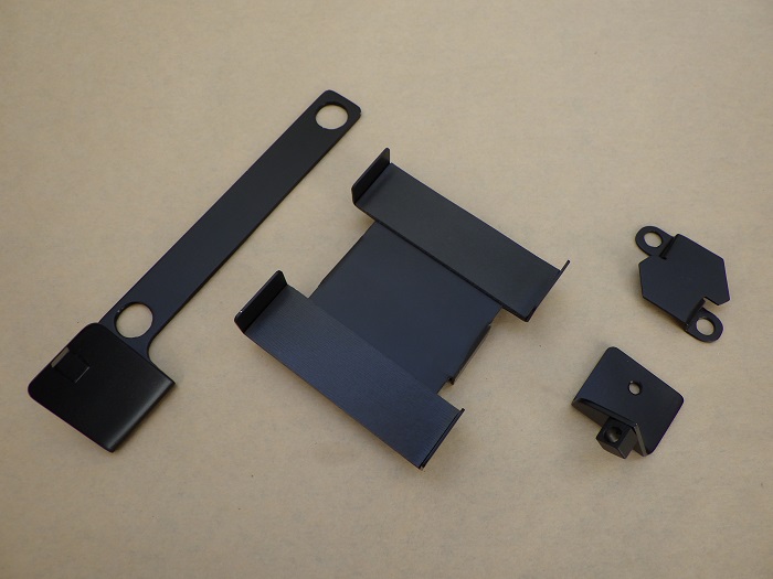
<Fabricated Brackets>
To mount the cameras and switch exactly where I want them, I made several custom brackets.
For details on how each bracket was made, check out the following maintenance records:
Unit bracket fabrication:
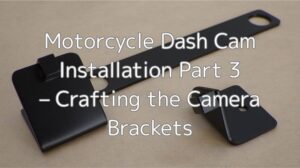
Camera bracket fabrication:
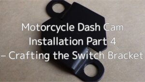
Switch bracket fabrication:
Removing Cowls and Panels
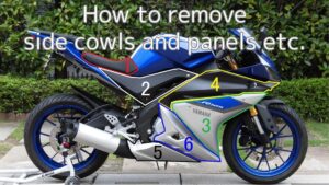
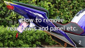
To install the drive recorder’s main unit, I first removed the side cowls, rear cowls, and box.
For detailed instructions, refer to these maintenance records:
How to remove side cowls and panels:
How to remove rear cowls and box:
Test Fitting the Main Unit
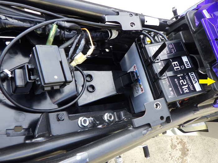
<Test Fitting the Main Unit>
I placed the unit on top of the battery and loosely routed the cables along the bike.
Since the unit sits directly above the battery, the 1-meter power cable ended up being way too long.
So, I temporarily routed it toward the rear and looped it back.
Routing the Unit’s Wiring
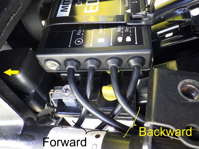
<Routing the Unit’s Wiring>
Four cables come out of the Main Unit:
- Front camera & switch cables → routed forward
- Rear camera & power cables → routed backward
Connecting the Intermediate Connector
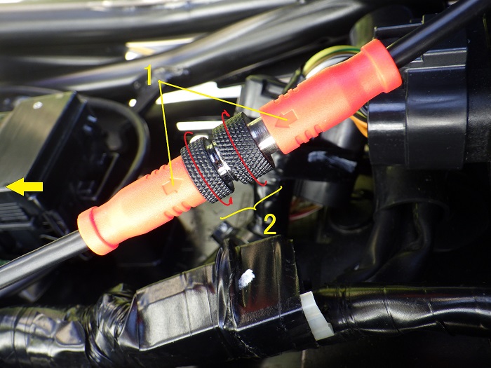
<Connecting the Intermediate Connector>
Connect the terminal-side power cable to the rearward-facing power cable:
- Align the arrows on the connector
- Tighten the locking ring
The connector includes an O-ring, so it should be well sealed against water.
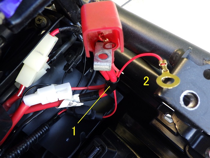
Routing the Power Cable
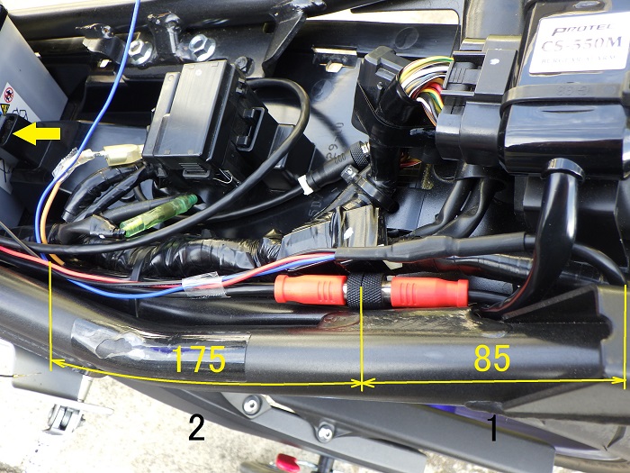
<Routing the Power Cable>
- Loop-back point
I decided to loop the cable back about 85mm from the intermediate connector. - Power wire (blue: 12V when IG ON, 0V when OFF) branching point
Branching occurs about 175mm from the connector.
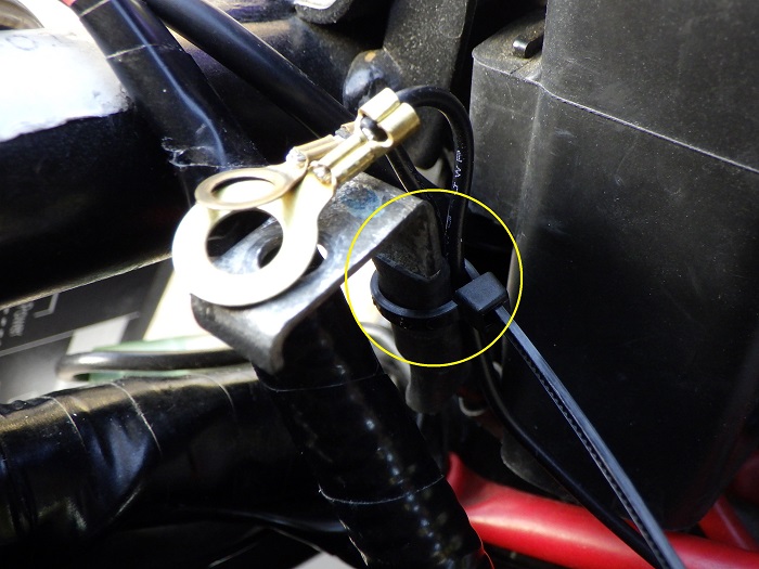
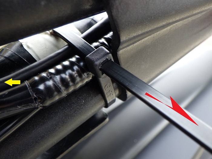
Securing the Loop-back Section
Now that I’ve decided on the cable routing (STEP 3–6), I removed the unit and started bundling the wires.
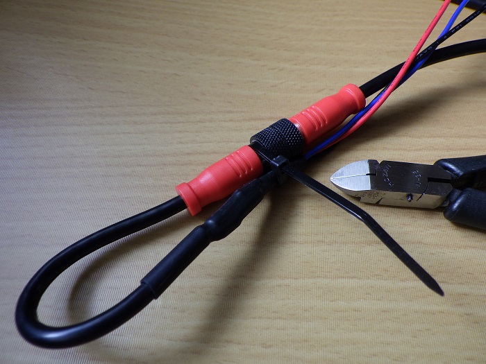
<Securing the Loop-back Section>
Using the groove in the intermediate connector, I secured the wiring with cable ties.
Installing Corrugated Tube 1
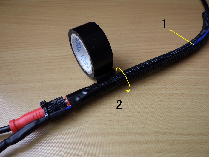
<Installing Corrugated Tube 1>
- Insert the power cable and three power wires into a 180mm-long corrugated tube (φ7)
- Wrap with insulating tape
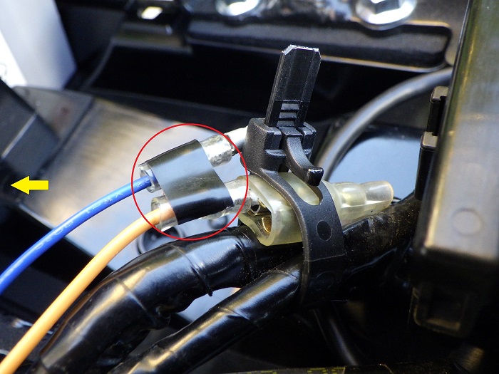
Branching the Power Wire
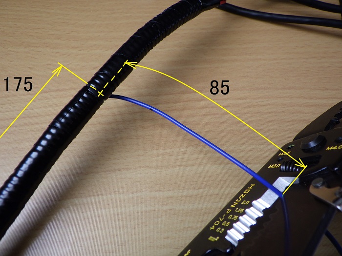
<Branching the Power Wire>
- About 175mm from the connector, pull out the blue power wire from the corrugated tube
- Cut the blue wire about 85mm from the branching point
Crimping the Power Wire Terminal
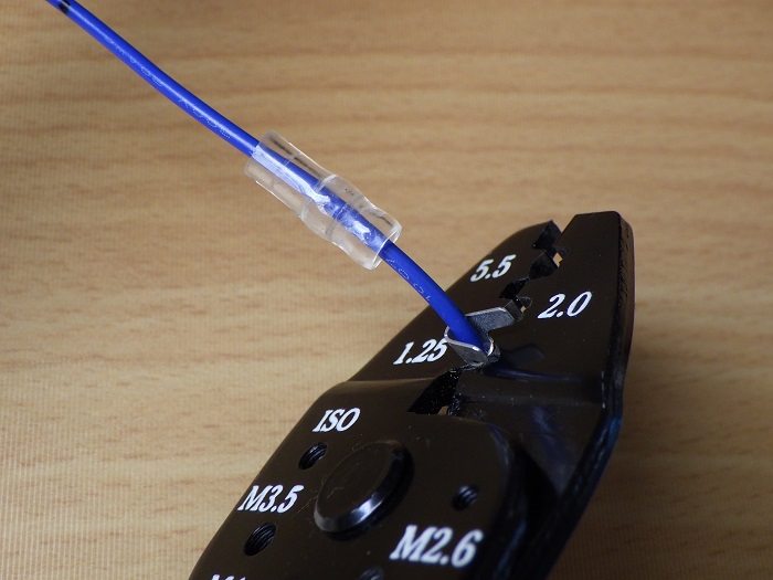
<Crimping the Power Wire Terminal>
Slide on the sleeve, strip about 8mm of insulation, fold the conductor, and crimp a bullet terminal using electrical pliers.
Installing Corrugated Tube 2
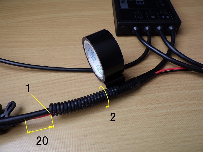
<Installing Corrugated Tube 2>
- Insert the switch cable and two power wires into an 80mm-long corrugated tube (φ7)
- Align the tube about 20mm from the fuse on the red power wire and wrap with insulating tape
*The photo shows the front camera cable bundled in, but I later revised the routing to use the switch cable instead.
Bundled Main Unit
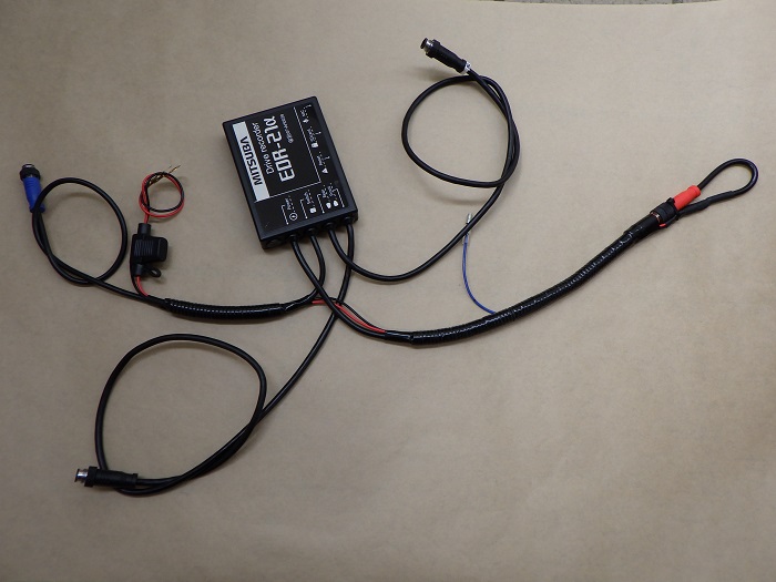
<Bundled Main Unit>
Here’s how it looks when bundled.
The corrugated tube helps protect and secure the power wires.
This setup allows easy removal and reinstallation.
Securing the Unit’s Wiring 1
Time to mount the unit onto the bike.
First, remove the battery.
(See maintenance record “Engine doesn’t start” STEP 6–11 for details.)
<Securing the Unit’s Wiring 1>
Route the forward-facing cables through the harness protector.
I temporarily routed the front camera and switch cables to the right side of the frame.
Looks like I forgot to tighten the fuse cap—just noticed from the photo.
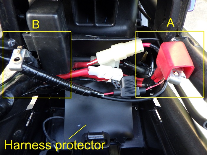
STEP 13 Section A
Secure the red (positive) power wire.
<STEP 13 Section A>
- Bundle with other power wires using insulating tape
- The ring terminal is too large to fit through the terminal cover, so I routed it directly to the battery’s positive terminal
Same routing as the burglar alarm wiring.
STEP 13 Section B
Secure the black (negative) power wire.
<STEP 13 Section B>
Secure it with a cable tie at the shrink tube section, and route the ring terminal to the battery’s negative terminal.
Then close the harness protector and reinstall the battery.
Mounting the Main Unit Bracket
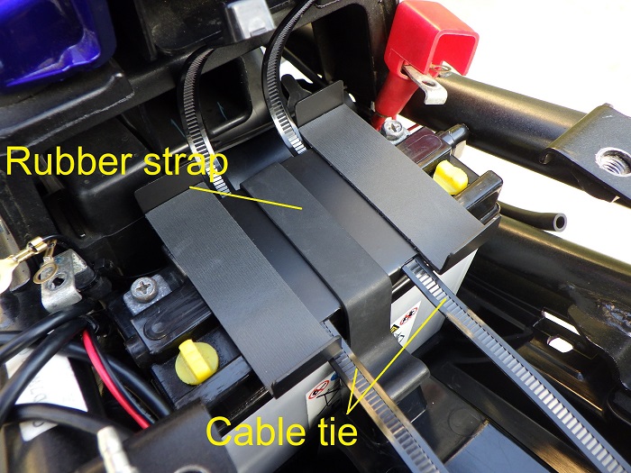
<Mounting the Main Unit Bracket>
Place the bracket on top of the battery and secure it using the battery’s rubber strap.
Also thread two cable ties under the bracket at this point.
Securing the Main Unit 1
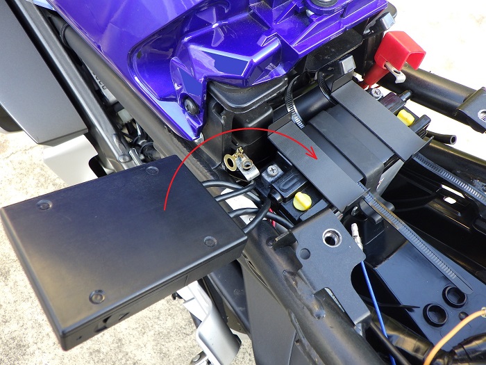
<Securing the Main Unit 1>
Flip the Main Unit over from its temporary position and place it on the frame side.
Securing the Main Unit 2
<Securing the Main Unit 2>
Place the unit onto the bracket and secure it with two cable ties.
To ease the cable bends, I mounted it slightly to the right.
Cutting cable Ties

<Cutting cable Ties>
Cut three cable ties holding the main harness from mid-left to rear using nippers.
Securing the Unit’s Wiring 2
<Securing the Unit’s Wiring 2>
Route the power and rear camera cables along the main harness:
- Loop-back section follows the burglar alarm wiring
- Intermediate connector is bulky, so I pushed it into the gap by shifting the main harness inward
- Rear camera cable is left loose for now
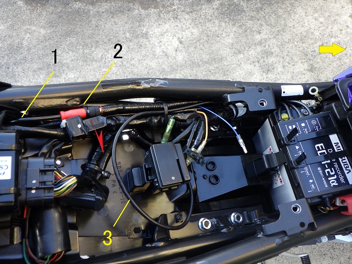
Securing the Unit’s Wiring 3
<Securing the Unit’s Wiring 3>
Now that the cables are routed, secure them with three cable ties.
Securing the Unit’s Wiring 4
<Securing the Unit’s Wiring 4>
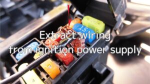
Temporarily fix the blue power wire near the ignition power wiring using insulating tape.
(For details on ignition power wiring, see the maintenance record “Extract wiring from ignition power supply.”)
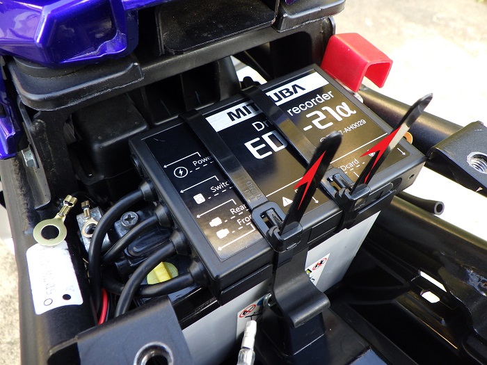
Installed Main Unit
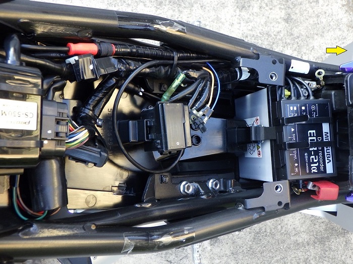
<Installed Main Unit>
The cameras and switch aren’t connected yet, but here’s how it looks.
Honestly, dealing with the excess wiring was a bit of a headache.
But since I might revise the routing later, this flexible approach feels like the right call.
Next Up: Motorcycle Dash Cam Installation Part 6 – Rear Camera Installation
3. Summary
Here’s a recap of the steps for mounting the Main Unit to the bike.
Once you’ve confirmed the mounting location, bundling the wiring with corrugated tubes makes future work easier.
Also, using black components and wires gives a factory-style finish and reduces the “aftermarket” look.
- Route excess power cables toward the rear for a cleaner look
- Bundle cables going in the same direction with corrugated tubing for easier organization
- Mount the unit bracket above the battery and secure it with the battery’s rubber strap