This is a continuation of the maintenance record ‘Replace tail tidy 1【Removal】’.
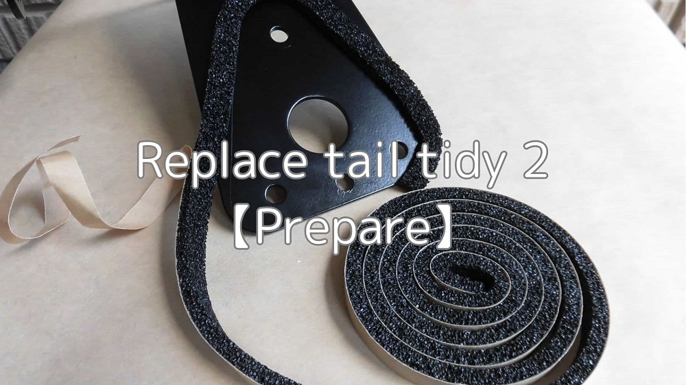
The tail tidy to be fitted is the R&G LP0162BK.
This is not a bolt-on kit and the following must be prepared.
- Wiring modifications to the license plate light
The license plate light is fitted with bullet terminals, but you will need to modify the wiring on the moto side. - Mounting the reflector on the bracket
Reflector is included in the kit, but you will need to think about how to install it to the bracket.
Although you may think for a moment that installing reflector is a ‘hassle…’, be sure to put it on for safety reasons.
In addition, the details are set out in Appendix 53 of Article 38 of the Safety Standards of the Road Vehicles Act.
If the standards are not met, the moto may be arrested for poor maintenance.
Furthermore, in addition to the two items above, I will devise a list of things I have noticed.
From this article you will know the following.
- Improvement to prevent water from entering the tail tidy mounting area
- Wiring modification of license plate light to facilitate removal and installation
- Fabrication of reflector
| Date | 4th July 2021 |
| Subjects | Tuning, Customize |
| Shop or DIY | DIY |
| Difficulty | |
| Working hours | 3 |
| Costs [Yen] | 14,461 |
1. Goods to use
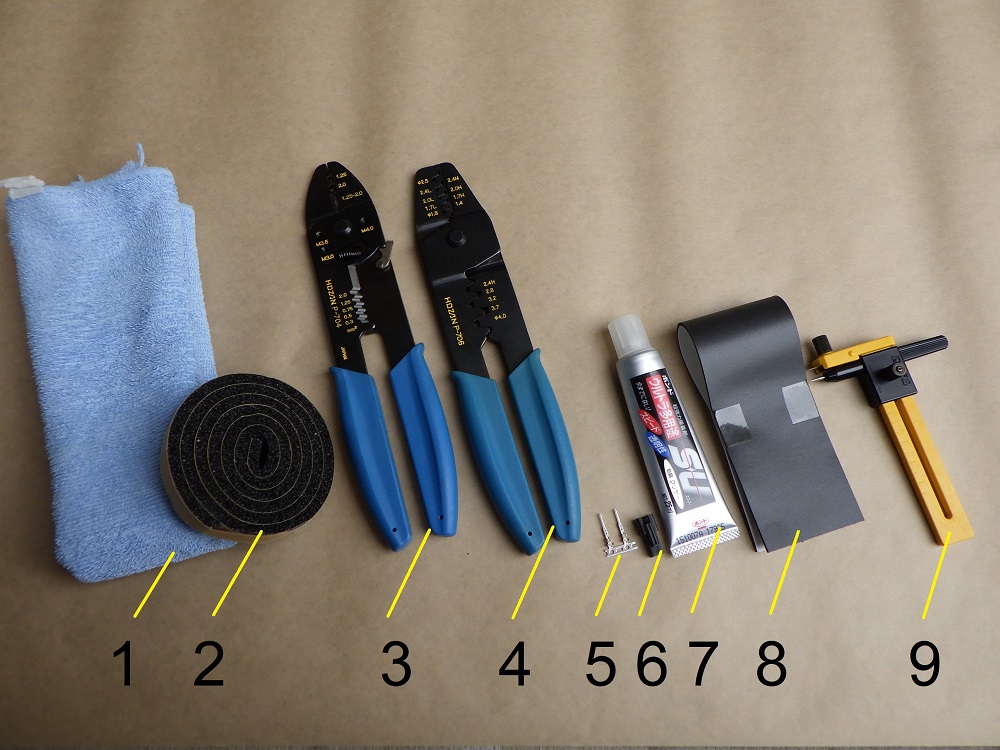
| No. | Name | Manufacturer | Products number | Quantity | Amounts[Yen] | Purchase this time |
| 1 | Microfiber cloth | – | – | 1 | (197) | |
| 2 | EPTSEALER (10mm) (Foam sealant) | Nitto Denko | 686 | 1 | (307) | |
| ST5 | Tail tidy | R&G | LP0162BK | 1 | 14,065 | ○ |
| 3 | Crimping tool | HOZAN | P-704 | 1 | 4,895 | |
| 4 | Crimping tool for open barrel contact | HOZAN | P-706 | 1 | 6,743 | |
| 5 | Pin contact (Terminal) | JST | SYM-001T-P0.6 | 2 | 14 | |
| 6 | Receptacle housing (Connector) | JST | SMR-02V-B | 1 | 15 | |
| 7 | Bond Ultra SU (Glue) | KONISHI | #04592 | 1 | (615) | |
| ST14 | Stay (15×100mm) | YAHATA NEJI | 186 | 1 | 198 | ○ |
| ST14 | Low head bolt M6×8 | YAHATA NEJI | 619 | 1 | 198 | ○ |
| ST14 | Flange nut M6 | – | – | 1 | 16 | |
| 8 | PORON Sponge roll (Sponge sheet with adhesive) | INOAC | L32-1.550MT | 1 | (549) | |
| 9 | Compass cutter | OLFA | 57B | 1 | (505) | |
| 28,317 | 14,461 |
2. Preparation for tail tidy installation (STEP 1-15)
Clean seat rail
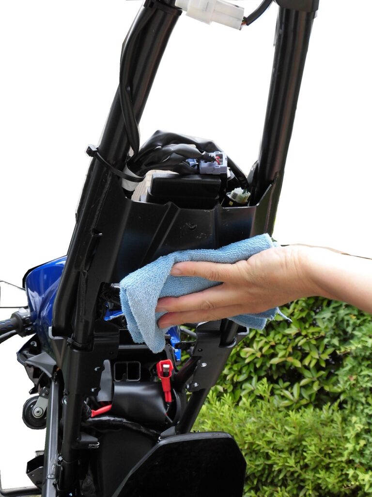
<Clean seat rail>
Before installing the tail tidy, wipe the seat rails with water using a microfiber cloth.
I would have liked to wash it with car shampoo, but decided not to as a number of non-waterproof connectors were used.
Flap guard mounting part
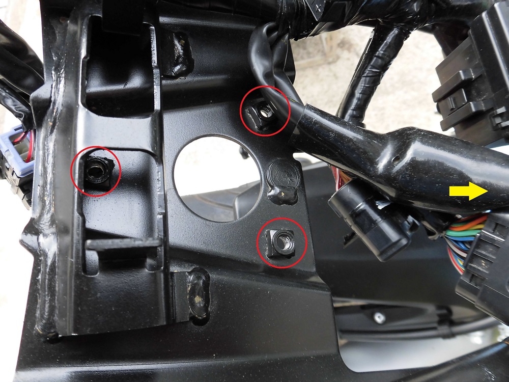
<Flap guard mounting part>
The photo shows the engine control unit moved out of the way.
You can see the three screws that hold the original flap guard in place.
So, the flap guard is firmly fixed to a bracket welded to the seat rail.
The tail tidy is also secured using these screws.
Stick foam sealing 1
Now, let’s prepare the moto body side.
The first step is to modify the mounting area.
After checking the mounting area, I noticed a gap between the mudguard and the seat rail bracket.
I decided to close this gap to prevent water from getting inside the mudguard.
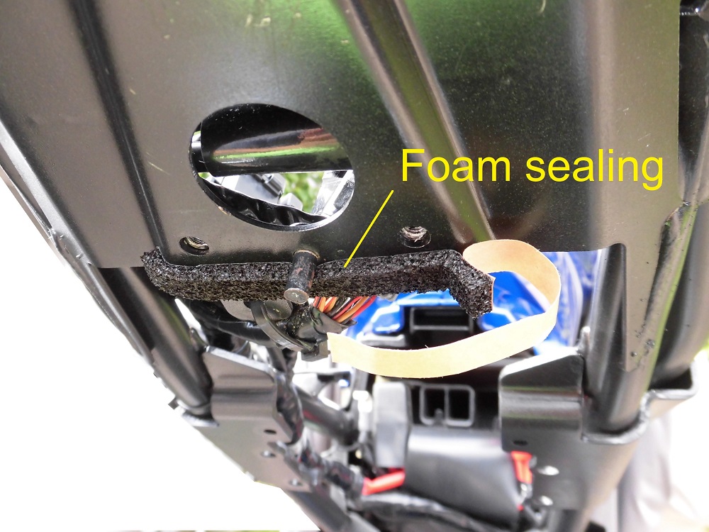
<Stick foam sealing 1>
Stick the foam sealant (10 mm wide), cut at about 100 mm, to the seat rail bracket.
Condition of installing mudguard
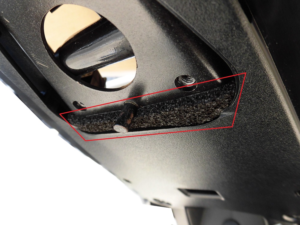
<Condition of installing mudguard>
Mudguard was put on to ensure that the foam sealant was sealing the gap.
Stick foam sealing 2
The next step is to improve to prevent water from entering the frame side from the top of the bracket.
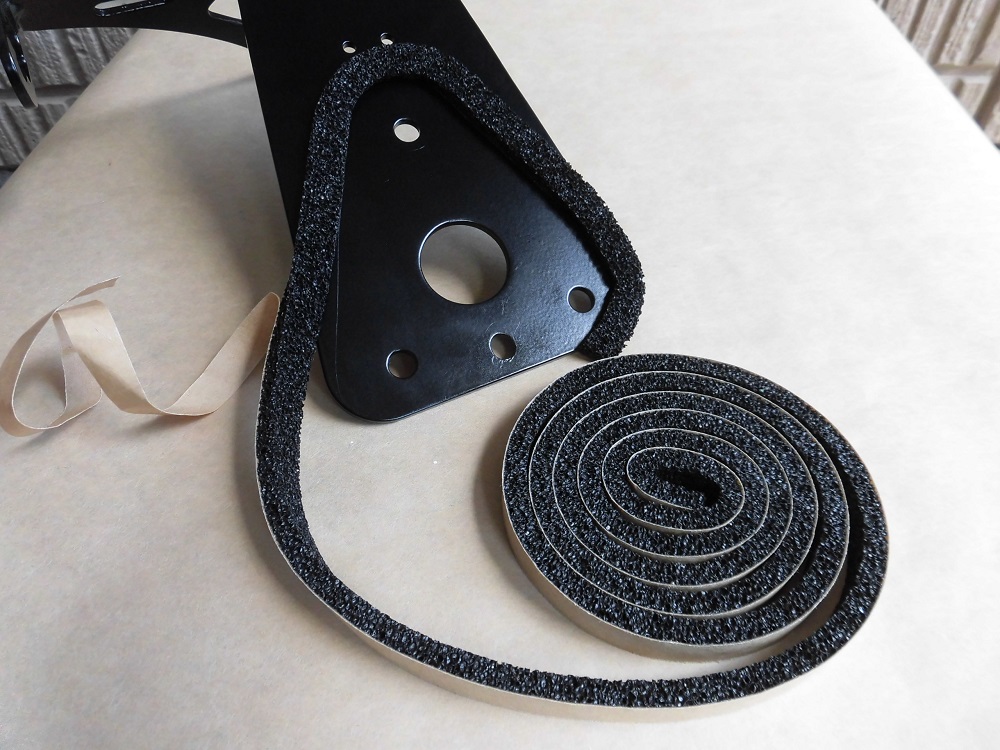
<Stick foam sealing 2>
The hole in the moto body is transferred onto the bracket.
Foam sealant (10 mm wide) was then sticked along the line.
- There are no waterproofing instructions in the manual.
- The grommet for the wiring is 15 mm thick and are designed to prevent water from getting in.
So, the top surface of the bracket seems to be originally designed to allow water to enter, I think.
Condition of sticking form sealing
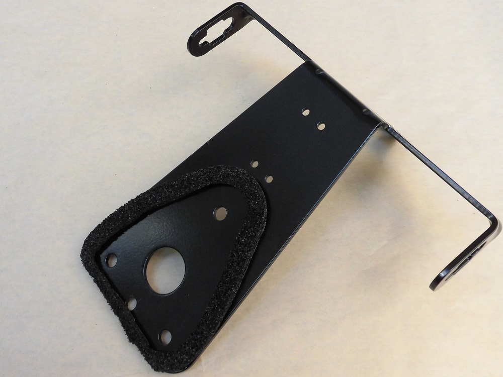
<Condition of sticking form sealing>
It’s a bit snarky, but this is what it looks like.
The left most part of the photo (the front part of the body) is 5mm wide to avoid interference with components.
I haven’t seen it, but I think it is the very shape of the original flap guard mounting area.
Remove wiring of license plate light
Next, the wiring is modified.
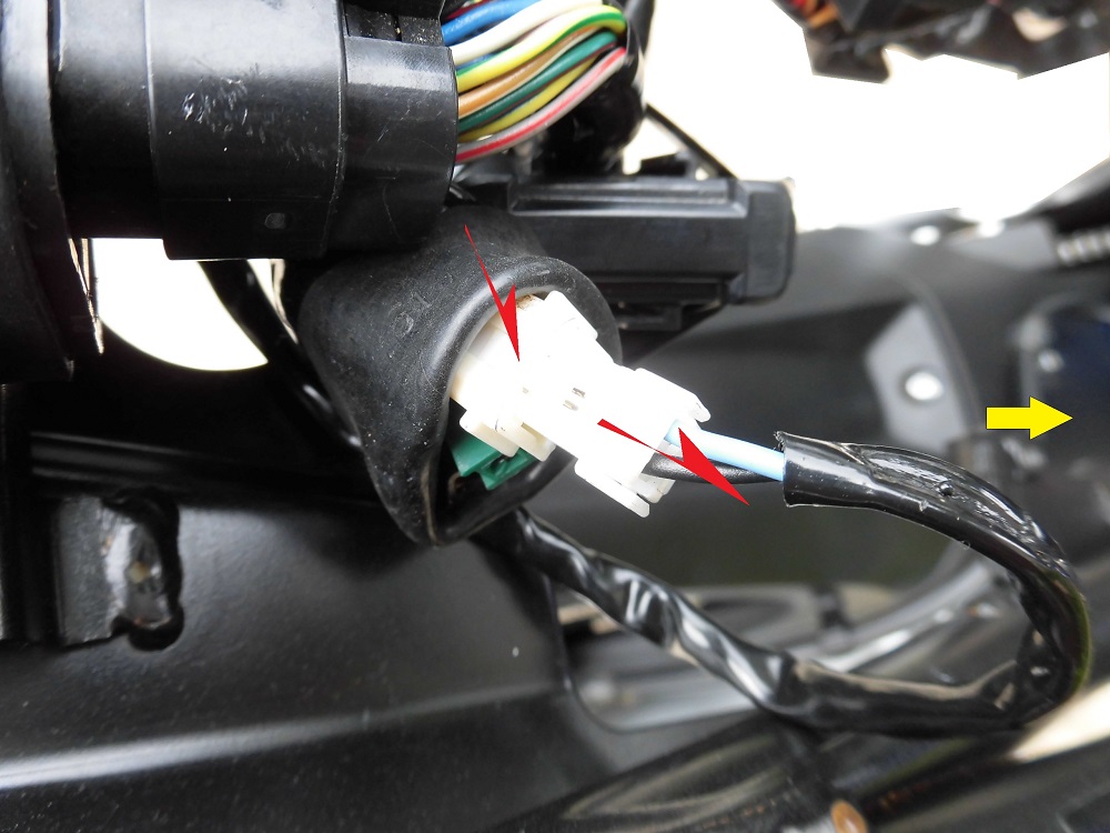
<Remove wiring of license plate light>
Disconnect the middle wiring connector of the license plate light.
Press and pull on the white protrusion to disconnect.
Check wiring of license plate light
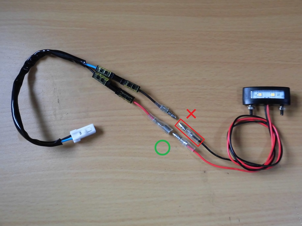
<Check wiring of license plate light>
Left: Middle wiring
Right: license plate light
The bullet terminals of license plate light are both male, so they don’t match the middle wiring.
I think the shortest way is to replace the part bracketed in red with a female terminal, but as it is a special opportunity, I decided to replace it with a connector I have on hand.
Disconnect general-purpose connectors
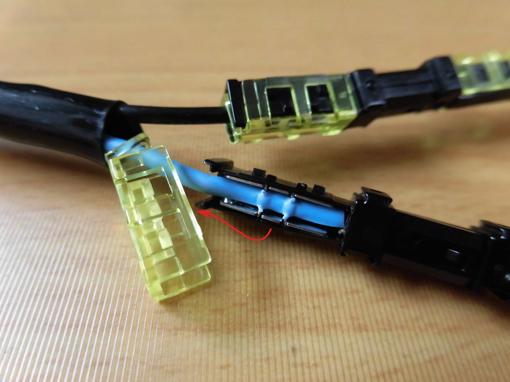
<Disconnect general-purpose connectors>
Disconnect the general-purpose connectors.
Lift the yellow lock and lift the wiring off.
I see, the method of securing the wiring is the same as with the scotch lock wire connector.
Process wiring
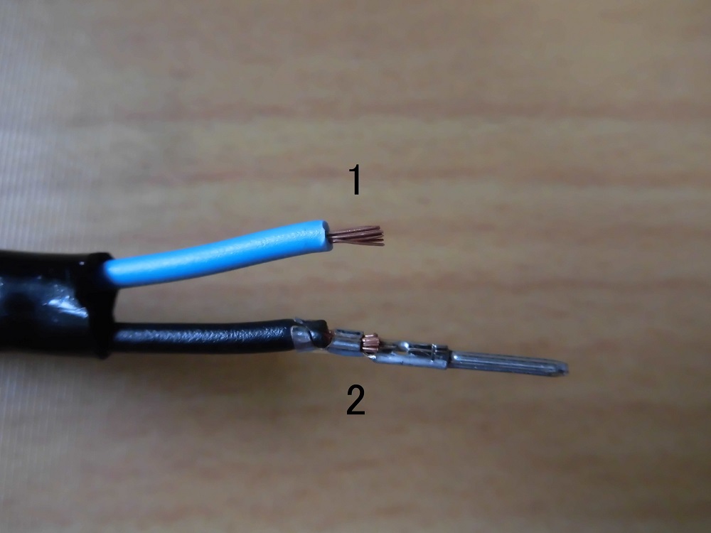
<Process wiring>
Cut the damaged part by connecting to general purpose-connectors,
- Peel off the sheaths.
- Crimp the crimp terminals.
Insert terminals
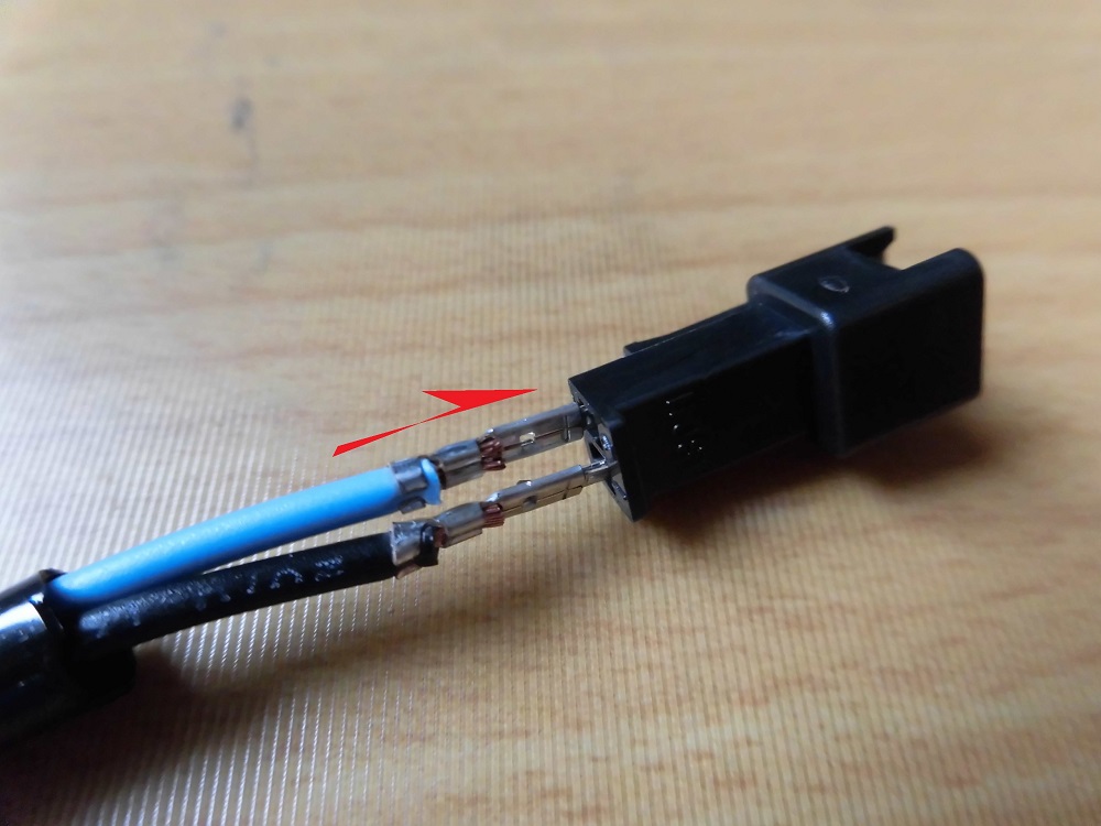
<Insert terminals>
Insert the crimped terminals into the connector.
Condition of connector
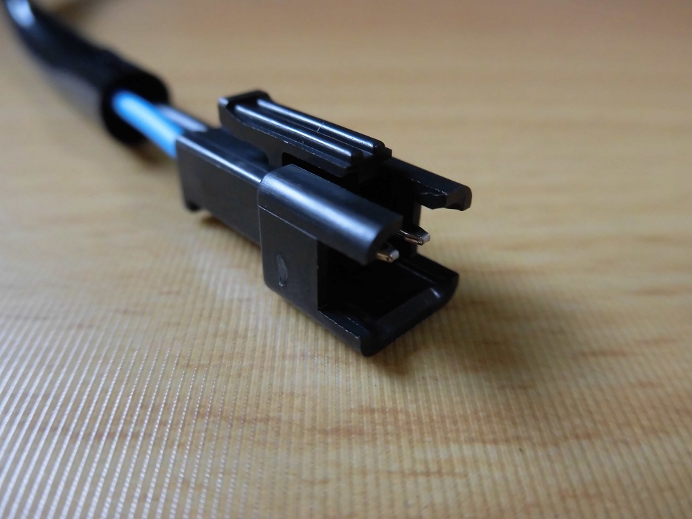
<Condition of connector>
This is how the middle wiring was done.
You may not have many chances to disconnect it, but it should be easier to remove and install this connector than bullet terminals.
(The wiring process for the license plate light will be done in the next maintenance record, ‘Replace tail tidy 3【Assembly】’.)
License plate light and shroud
Now, I will prepare the parts to be fitted to the bracket.
I’ll start with the license plate light.

<License plate light and shroud>
The instructions say in bold print ‘Glue the shroud to the license plate light’, but at first, I didn’t understand what they were talking about.
I didn’t understand what it meant at first, because the shroud and license plate light were temporarily assembled as one piece.
In fact, when I accidentally dropped it, the shroud came off and I didn’t realize it until later.
So, the shroud and license plate light are glued together.
There could be a case where you install it without noticing this, and after driving for a while, the shroud is gone.
Reflector components
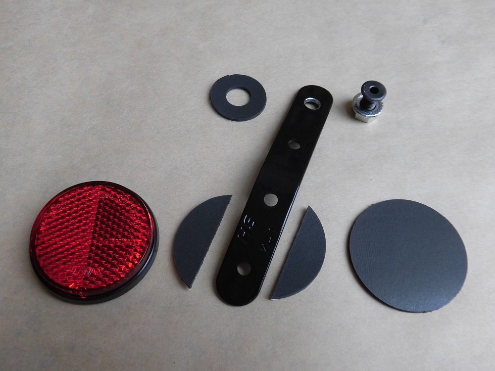
<Reflector components>
Next, prepare the reflector.
Only the round reflector was included in the kit.
So, other than that, I prepared the parts myself.
- Bracket
Prepared 100 mm stay, bent to be close to vertical when fitted. - Bolt and nut to fix the bracket
Prepared a low head bolt as they overlap the license plate - Reflector support
Prepared sponge sheet with adhesive to prevent it from falling off
By the way, I used the reflector from the kit, but I can also use commercially available reflector (the type that clips together with the license plate) that I can remove.
Condition of installing reflector
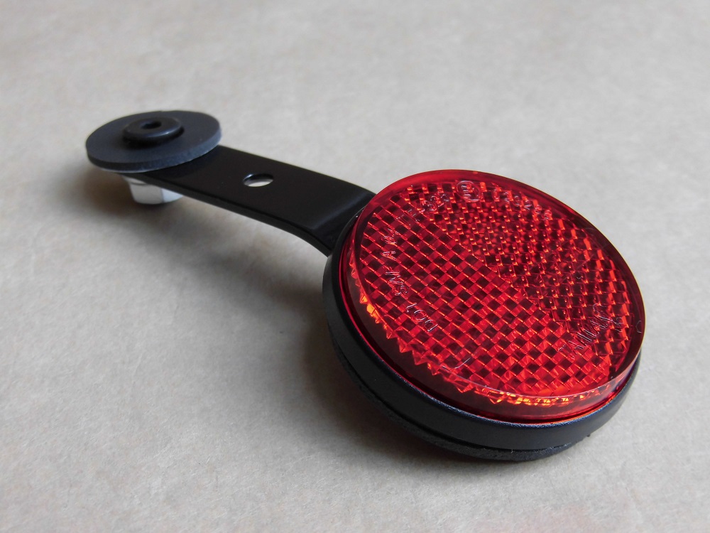
<Condition of installing reflector>
This is how it turned out.
The reflector is fixed with double-sided tape, but I felt that it might peel off if only one side was used, so I reinforced it from the back side so that it wraps around the stay.
The back side is now thicker, but it is very strong.
It seems unlikely to fall off easily.
This time, I bought a compass cutter and cut out the sponge sheet, but it was fun, and I cut it in vain.
Continue to ‘Replace tail tidy 3 【Assembly】’.
3. Summary
The following is a summary of the preparations that must be made before a tail tidy can be fitted.
Even if the kit is model-specific, some modification is often required.
It may be a hassle to modify the tail tidy, but it also gives you room for ingenuity, I think.
Next time, I will finally install the license plate light, reflector, turn signals, etc. on the tail tidy.
- Foam sealant to prevent water getting inside the mudguard
- Connector on the wire for license plate light to facilitate removal and installation.
- Note that the license plate light and shroud are not glued together.
- Reflector can be modified with stay and sponge sheet.
