This is a continuation of the maintenance record ‘Replace tail tidy 3 【Assembly】’.
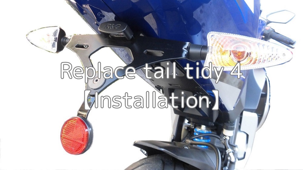
The temporarily assembled tail tidy (R&G’s LP0162BK) is installed on moto’s body.
I thought I had the wiring together and all I needed to do was installed it on the moto…
From this article you will know the following.
- How to install tail tidy
- How to fix and put together the wiring
- Points to note when using the tester
| Date | 17th July 2021 |
| Subjects | Tuning, Customize |
| Shop or DIY | DIY |
| Difficulty | |
| Working hours | 1 |
| Costs [Yen] | 0 (Use what I have) |
1. Goods to use
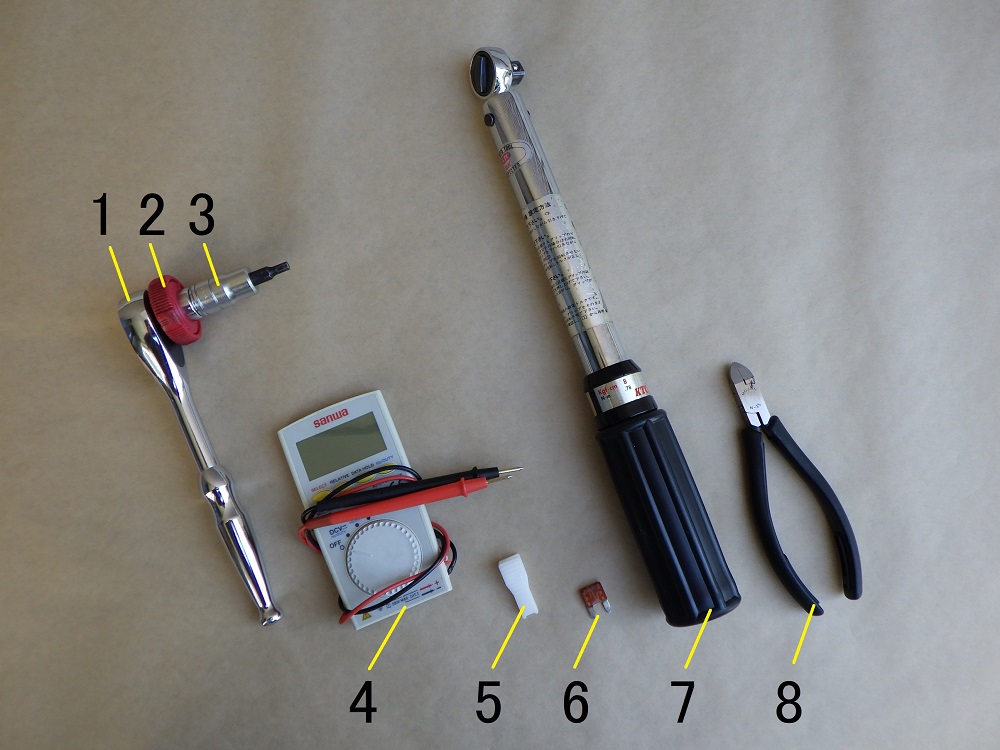
| No. | Name | Manufacturer | Part number | Quantity | Amounts[Yen] |
| 1 | Ratchet wrench | KTC | BR3E | 1 | 6,182 |
| 2 | Quick spinner | KTC | BE3-Q | 1 | 2,046 |
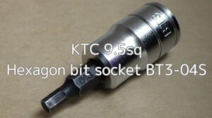
| 3 | Bit socket (6mm) | KTC | BT3-04S | 1 | 1,012 |
| 4 | Digital multi meter | Sanwa Electric Instrument | PM3 | 1 | 4,950 |
| 5 | Huse clips | EMON | 1280 | 1 | 109 |
| 6 | Flat mini fuse (7.5A) | – | – | 1 | 109 |
| 7 | Torque wrench (Small) | KTC | CMP0252 | 1 | (44,990) |
| 8 | Miniature nipper | HOZAN | N-35 | 1 | 3,465 |
| 62,863 |

2. Install tail tidy (STEP 1-15)
Run wirings through hole
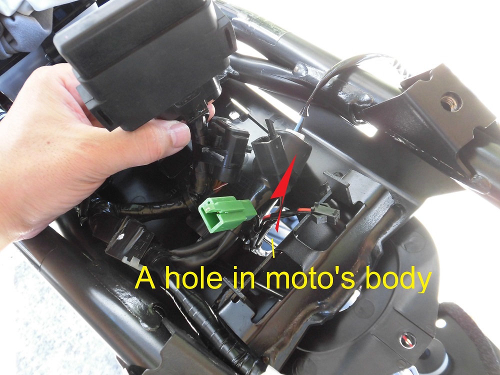
<Run wirings through hole>
Run the wirings through a hole in the moto’s body.
Mounting part of tail tidy
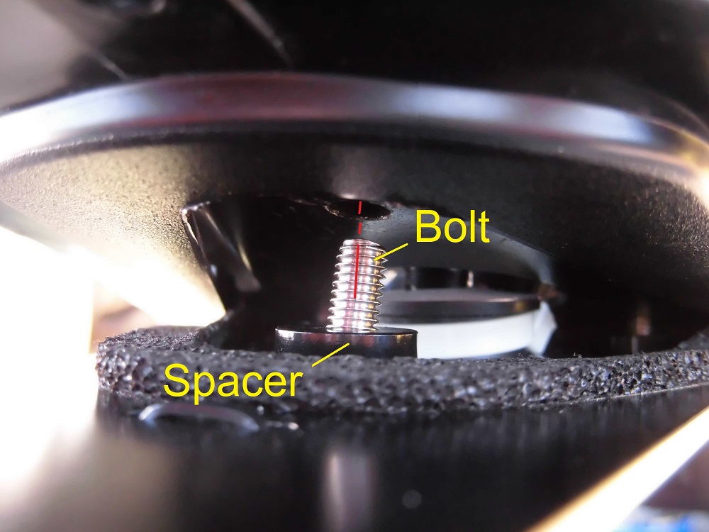
<Mounting part of tail tidy>
To install the tail tidy, run the bolt through the bracket and spacer and tighten them to the moto’s body.
Install tail tidy 1
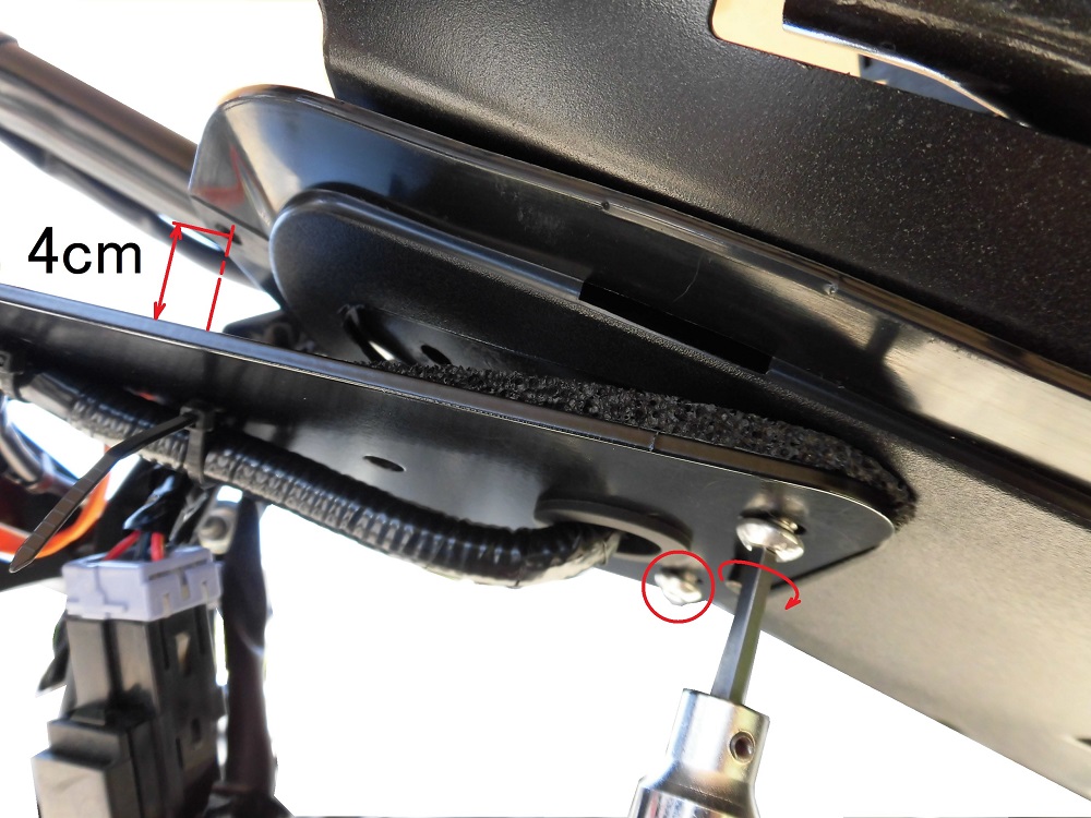
<Install tail tidy 1>
Insert the two front mounting bolts from underneath the bracket and pass the spacers (3 mm thickness) through.
Then, using a ratchet wrench with a hexagon socket (4 mm), temporarily tighten the bolts to the moto’s body.
Tighten the bolts temporarily until the gap at the rear end of the mudguard is about 4 cm.
If you tighten the bolts completely, you will not be able to insert the push rivet in the rear cowl.
Connect wirings
The tail tidy is temporarily installed, but the wirings are connected.
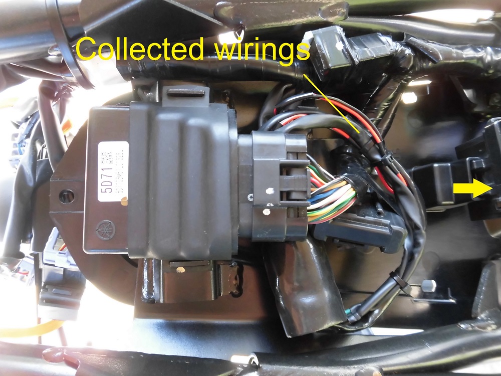
<Connect wirings>
The wiring was connected by bypassing the front of the engine control unit.
In the instructions, the work is done without removing the box, so the wirings need to be routed and connected in the limited space available.
In this case, the work was easier because the box was removed.
Confirm voltage value
Before installing the rear cowl, check that the license plate light and turn signals are illuminated.
When the ignition switch is switched on…
‘Hey, the license plate light doesn’t come on!’
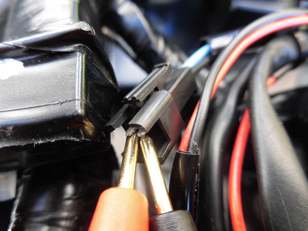
<Confirm voltage value>
I put a tester to the terminals in the connector to see if 12V is coming to the wiring on the body side…
‘BANG!’
‘It’s short-circuited!’
‘Oh, what am I doing?’
This is what happens when I apply a test lead at this narrow pitch… (I didn’t realize this before I did it.)
Fuse box
Naturally, it is not energized (it has been broken), so first check the fuses.
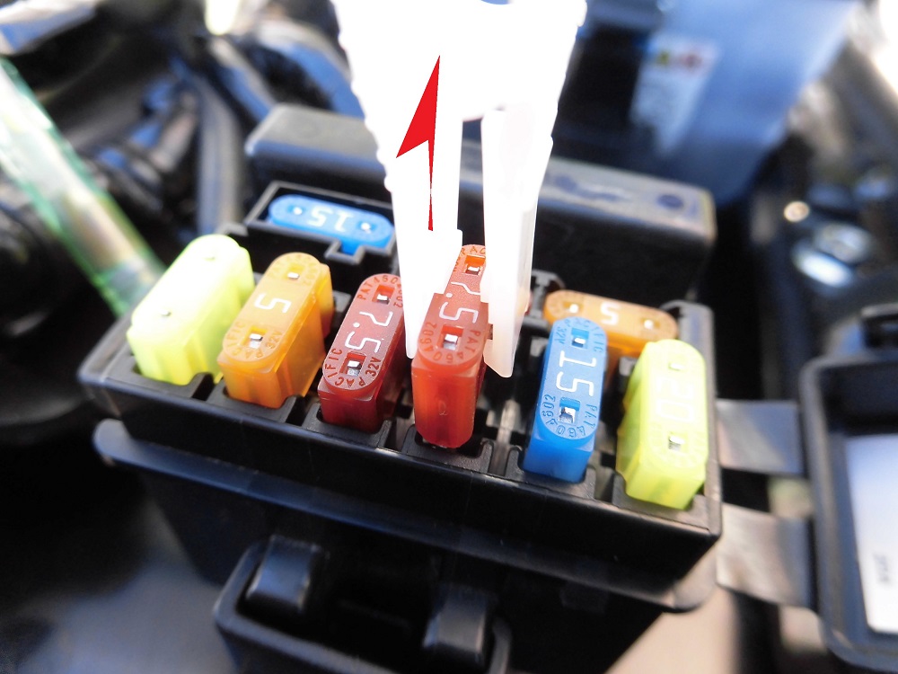
<Fuse box>
Open the fuse box and remove the 7.5A signal fuse with the fuse clip…
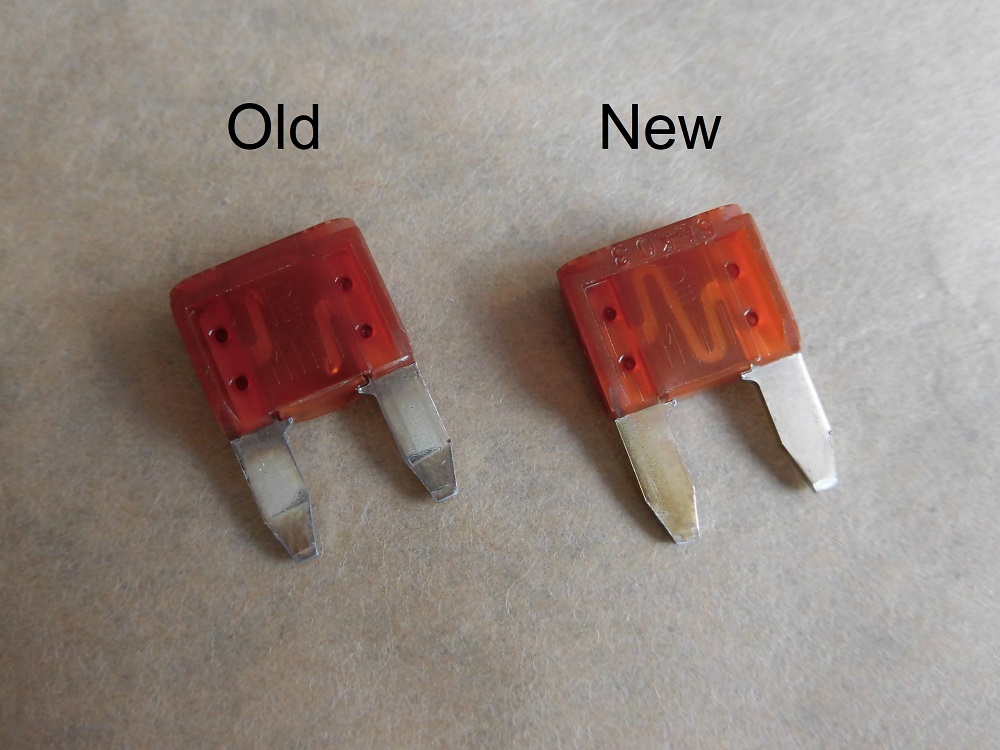
Comparison of fuses
<Comparison of fuses>
Left: Blown fuse
Right: Spare fuse
‘Oh, it’s still out.’
The middle element was cleanly missing.
Fortunately, there was a spare fuse in the fuse box, so I replaced it.
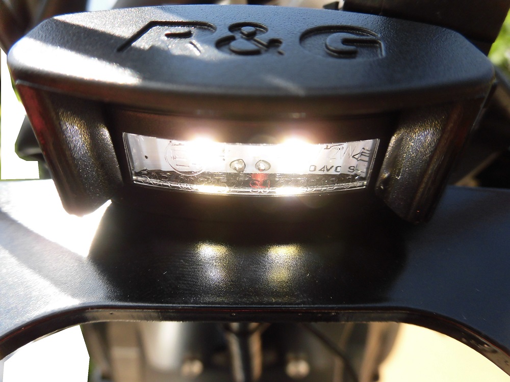
Illuminated license plate light
<Illuminated license plate light>
It turns out that the license plate light did not come on because the terminals in the connector were reversed.
The license plate light is an LED and has polarity.
So, if it does not come on, you may want to try swapping the terminals in the connector first.
Install box and rear cowl and so on
Then install the box, rear cowl, etc.
(For details, see maintenance record ‘How to install rear cowls and panel etc.’ STEP 8 onwards).
Insert push rivet
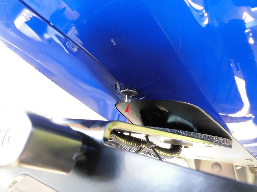
<Insert push rivet>
Then insert the push rivet at the rear end.
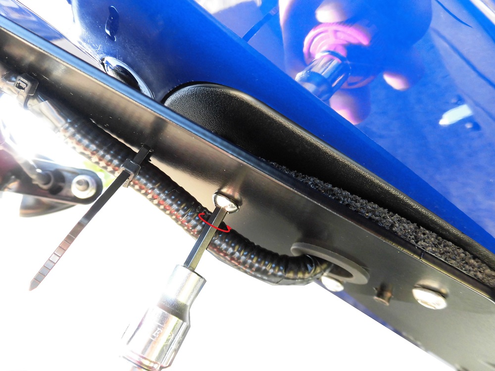
Install tail tidy 2
<Install tail tidy 2>
Do the same for the rear installing bolts, passing the spacers (6 mm thickness) through them, then tightening them to the moto’s body.
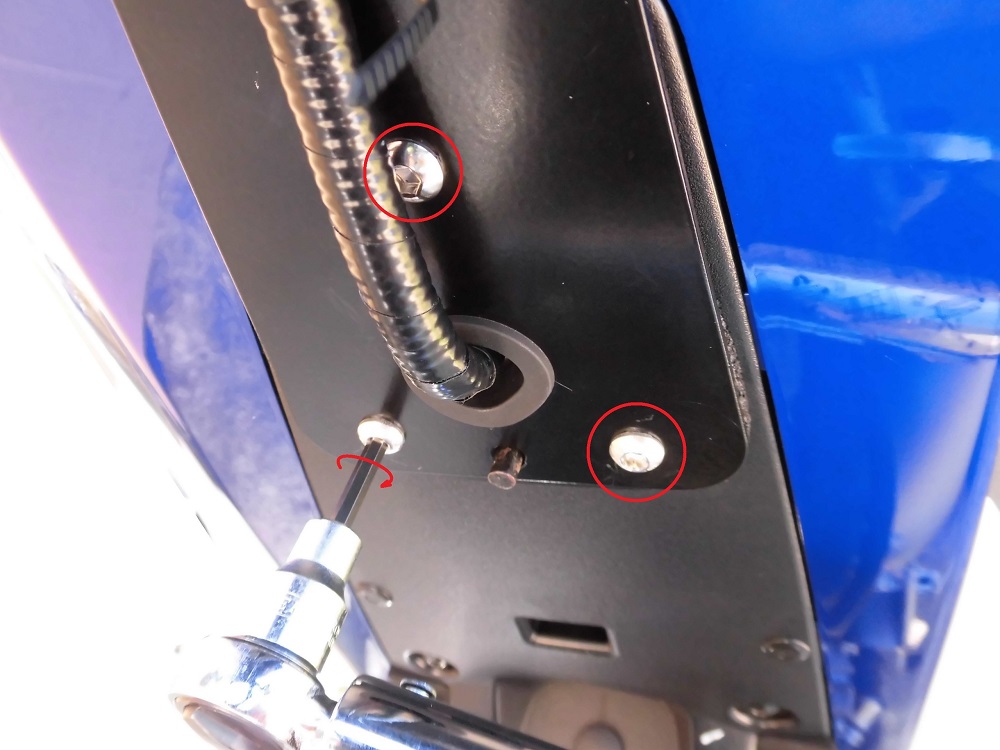
Install tail tidy 3
<Install tail tidy 3>
Using a torque spanner with a hexagon socket (4 mm), the three bolts were tightened to 15 N-m.
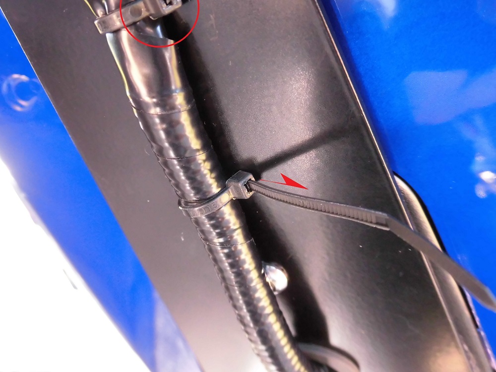
Tightening of cable ties
<Tightening of cable ties>
Tighten the ties that were temporarily tightened in STEP 14 of the maintenance record ‘Replace tail tidy 3’.
The excess band was cut with nippers.
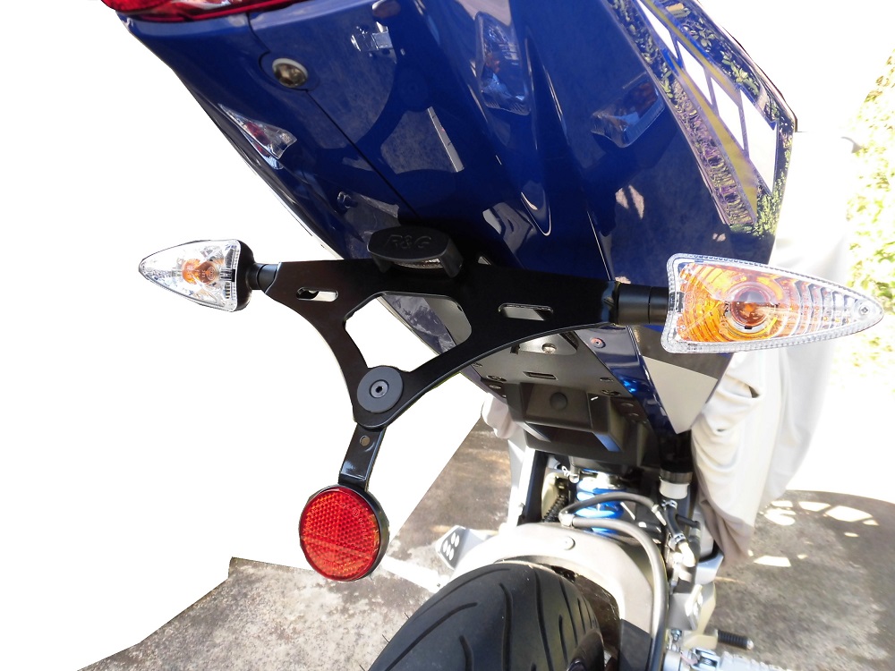
Installed tail tidy
<From behind>
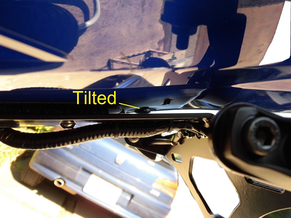
<From side>
It came together like this.
The push rivet on the top side of the tail tidy is tilted.
This may be because the hole in the rear cowl has been shaved and is slightly larger in diameter. (Shame!).
Comparison before and after
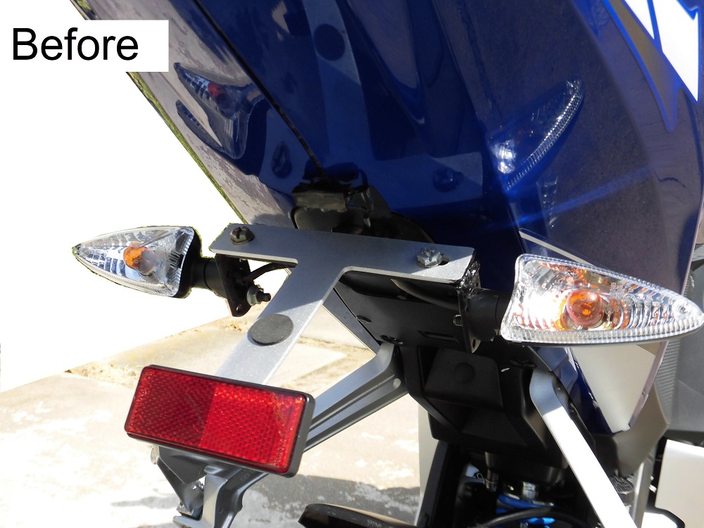
<Before>
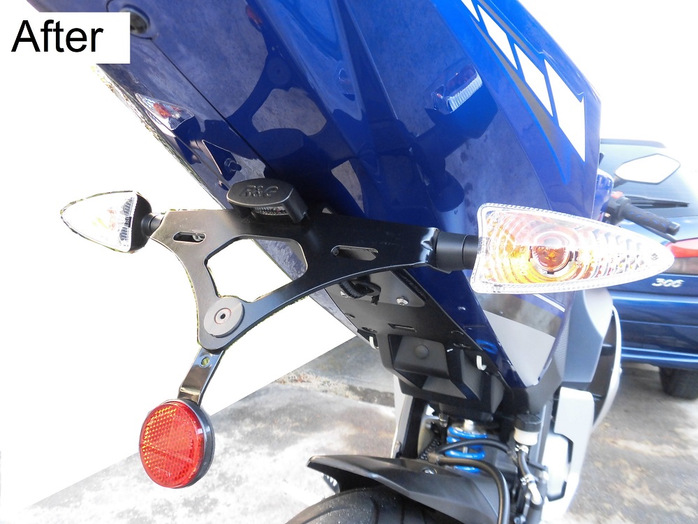
<After>
Made by R&G, it’s nice and simple.
The angle of the license plate has also been settled.
3. Summary
This section summarizes the wiring connections for the license plate light and turn signals and the installation of the tail tidy.
There were some mistakes in the wiring process on the body side, but I was able to install it safely.
This time, I understood how the wiring was handled.
So, I will be able to work on it smoothly next time.
- The use of a general-purpose connector for the connection of the license plate light has made it easier to remove and install.
- The wiring routing on the body side was also neatly organized.
- When touching probes to the terminals, make sure beforehand that there is no short-circuit.
Replacing the tail tidy, - Removal and installation have been made easier.
- The angle of the license plate is now correct.
- The light from the license plate light now shines evenly.
