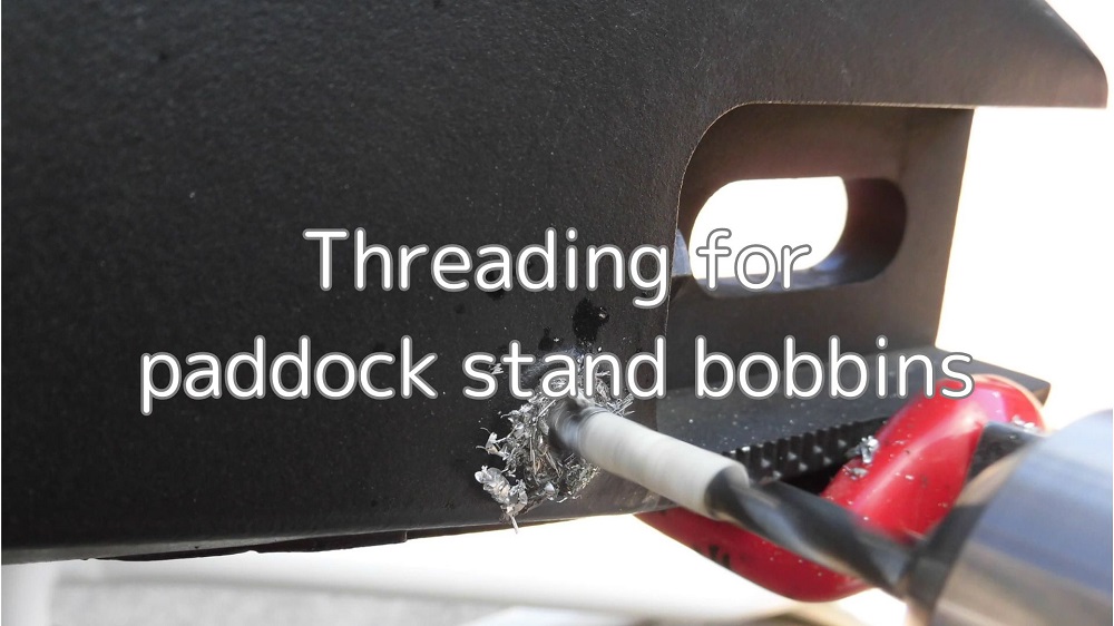
To rear paddock stand bobbins (hereafter described as the bobbins) to the YZF-R125 (5D7W), a threaded hole must be machined on the swingarm.
The screw size for the bobbins used by Yamaha is M6 with a pitch of 1.0.
These threaded holes are machined using a drill and tap.
From this article you can find out the following.
- The procedure for threading in holes
- How to drill a hole in the middle of the seat
- How to process the screw
- Condition after machining
| Date | 17th June 2023 |
| Subjects | Tuning, Customizing |
| Shop or DIY | DIY |
| Difficulty | |
| Working hours | 6 |
| Costs [Yen} | 3,124 |
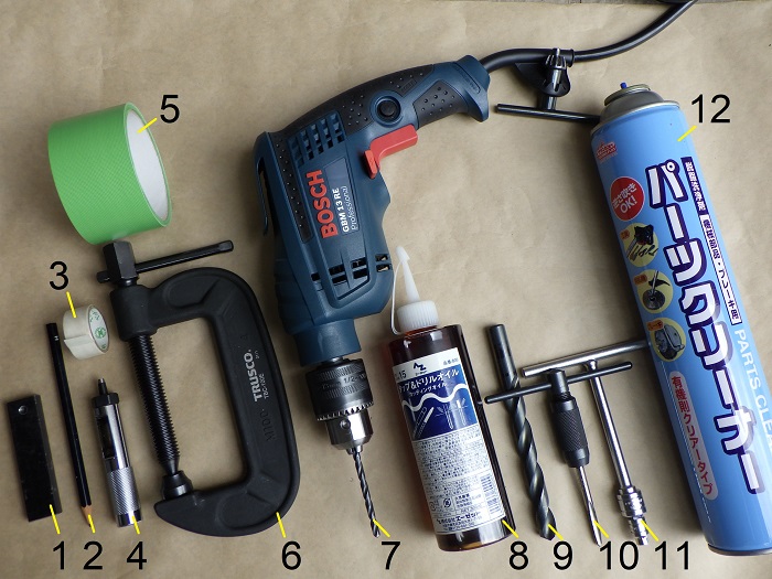
1. Goods to use
| No. | Name | Manufacturer | Parts number | Quantity | Amounts[Yen] | Purchasing this time |
| 1 | Guide bar | – | – | 1 | (100) | |
| 2 | Pencil | – | – | 1 | (100) | |
| 3 | Masking tape | – | – | 1 | (100) | |
| 4 | Punch(φ4) | STRAIGHT | 19-569 | 1 | 3,950 | |
| 5 | Curing tape | – | – | 1 | (100) | |
| 6 | Vice | TRUSCO | TBC-100E | 1 | 2,179 | ○ |
| 7 | Drill 5.0 mm (+Electric drill) | MITSUBISHI MATERIAL | BTSDD0720 | 1 | 945 | ○ |
| 8 | Cutting oil | AZ | 800 | 1 | 880 | |
| 9 | Drill 13 mm | MITSUBISHI MATERIAL | BSDD1300 | 1 | 2,739 | |
| 10 | Tap (M6 x 1.0) (+Handle) | – | – | 1 | 373 | |
| 11 | Socket (5.5 mm) (+Conversion socket and T-handle) | KTC | B2-055W | 1 | 800 | |
| 12 | Parts cleaner | – | – | 1 | (300) | |
| 12,566 | 3,124 |
2. Threading for bobbins (STEP 1-23)
Seat of bobbin
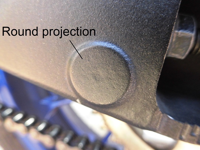
<Seat of bobbin>
The round projection at the rear of the swingarm, slightly before the chain adjustment bolt, is the seat of the bobbin.
Drill holes here and process the threads.
Drilling the holes with a drill can easily result in a 1 mm deviation of the center, so I have to find a way to drill in the middle of the seat.
Guide bar
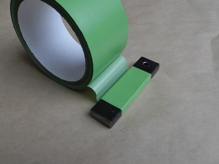
I made something like this.
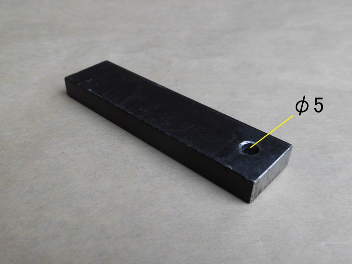
<Guide bar>
Guide bar with 5 mm holes drilled.
I decided to apply the guide to the drill to prevent it from being misaligned.
The flat bar was used in a vise so that it could be clamped onto the swingarm.
This should minimize the misalignment of the holes.
Remove rear wheel
Now let’s get to work.
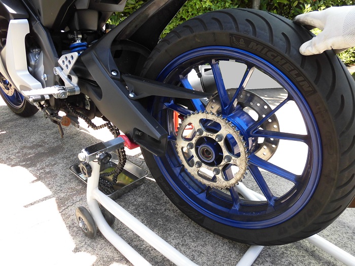
<Remove rear wheel>
Remove the rear wheel to make it easier to apply the guide bar to the swingarm.
Originally, it is not necessary to remove the rear wheel if only drilling and threading is required, but I take all precautions.
How to remove the rear wheel is summarized separately.
With rear wheels removed
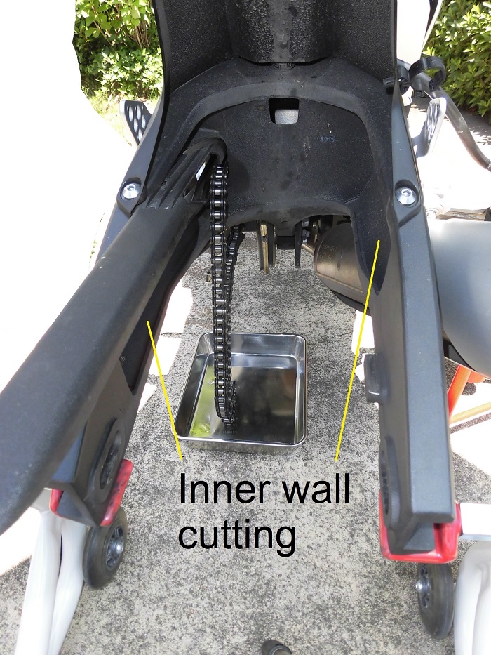
<With rear wheels removed>
It’s just a swingarm, so it’s clean and clear.
The arms have a different shape on the left and right side, but the inner wall cutting is also completely different.
Is this used to balance the rigidity of the left and right sides?
Unless otherwise stated, the photos below are of the left side.
Marking of hole position 1
Drill a 5 mm hole as a preparation hole for machining an M6 screw.
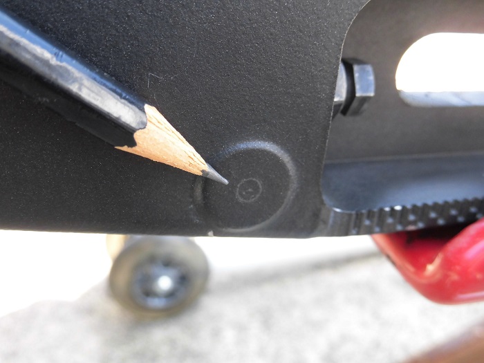
<Marking of hole position 1>
Mark ø4 on the seat with a pencil.
At this point, mark carefully, as it would be meaningless if the position is displaced.
Preparation of masking tape
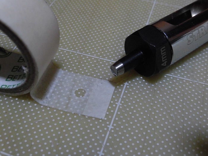
<Preparation of masking tape>
Use a punch to make a ø4 hole in the masking tape.
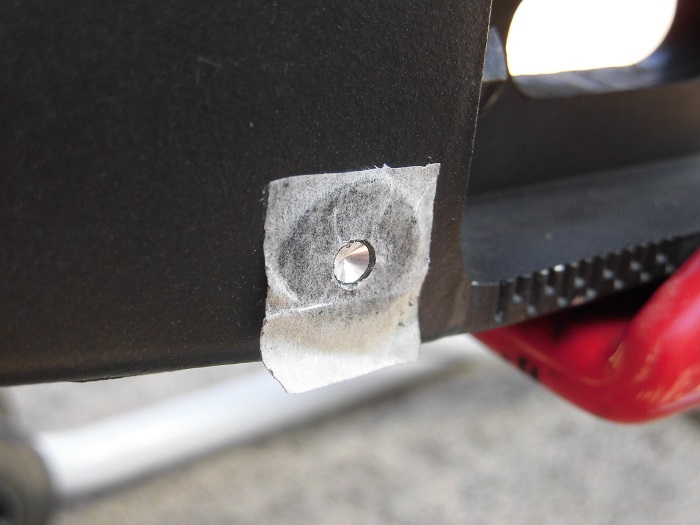
Marking of hole position 2
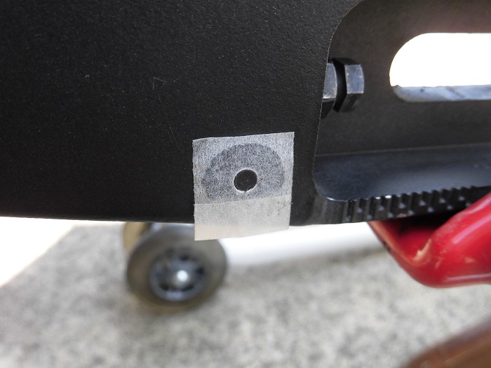
<Marking of hole position 2>
As a pencil would not stand out, apply the masking tape prepared in STEP 6.
Guide bar curing
<Guide bar curing>
Wrap the curing tape around the guide bar for about three turns to avoid scratching the swingarm.
Installation of guide bar 1
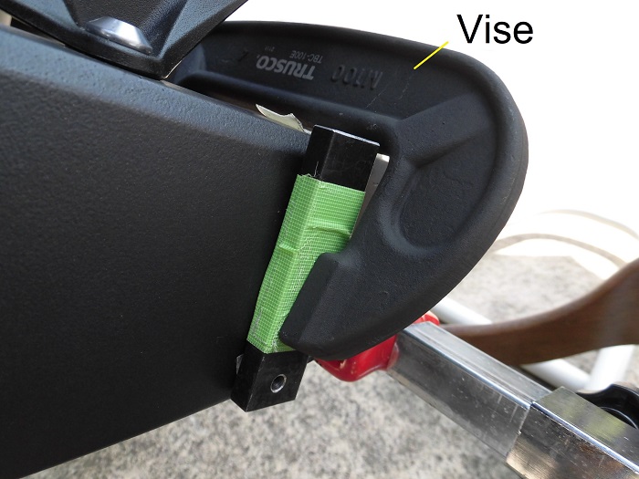
<Installation of guide bar 1>
Align the holes in the masking tape with the holes in the guide bar.
Then, use a vise to clamp the guide bar to the swingarm.
Installation of guide bar 2
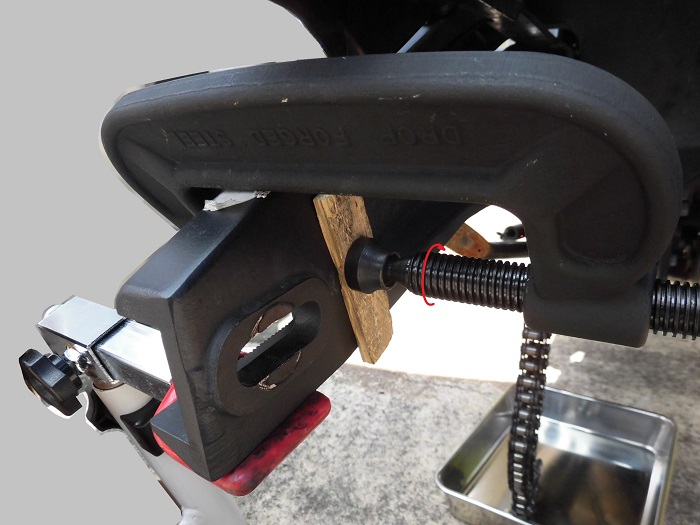
<Installation of guide bar 2>
To prevent damage to the swingarm, a wooden board was inserted inside.
Check hole orientation
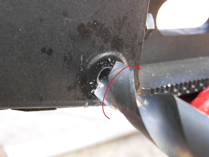
The drill was inserted upside down into the guide bar to check the direction of the hole.
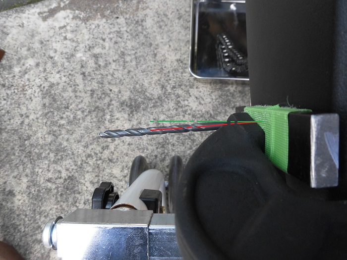
<Check hole orientation>
The drill is pointing at an angle to the direction of the swingarm.
If we drill the hole as it is, the bobbin will be tilted.
I have no choice but to drill a hole just 2 or 3 mm into the surface of the swingarm and then remove the guide bar.
Drilling 1
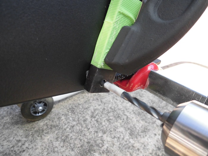
<Drilling 1>
Insert an electric drill with a 5 mm drill attached into the hole in the guide bar and drill a small hole.
Then remove the guide bar.
With a hole drilled 1
<With a hole drilled 1>
The hole has been drilled in roughly the desired position.
The hole is slightly off-center, but without the guide bar it would not have been possible to drill in this position.
Drilling 2
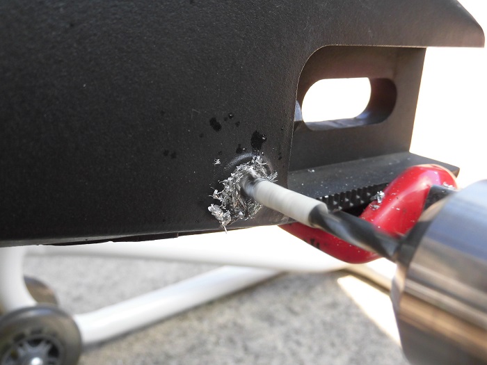
<Drilling 2>
Drill the holes with an electric drill without a guide bar.
While applying cutting oil, I carefully proceeded to open perpendicular to the seat.
The depth of the hole was set at 20 mm considering the following.
- Length of bobbin screw: 13 mm
- Depth at which the tap can be threaded: About 7 mm from the cutting edge
Masking tape was also attached at a position 20 mm from the drill’s cutting edge to serve as a guide for the depth of the hole.
With a hole drilled 2
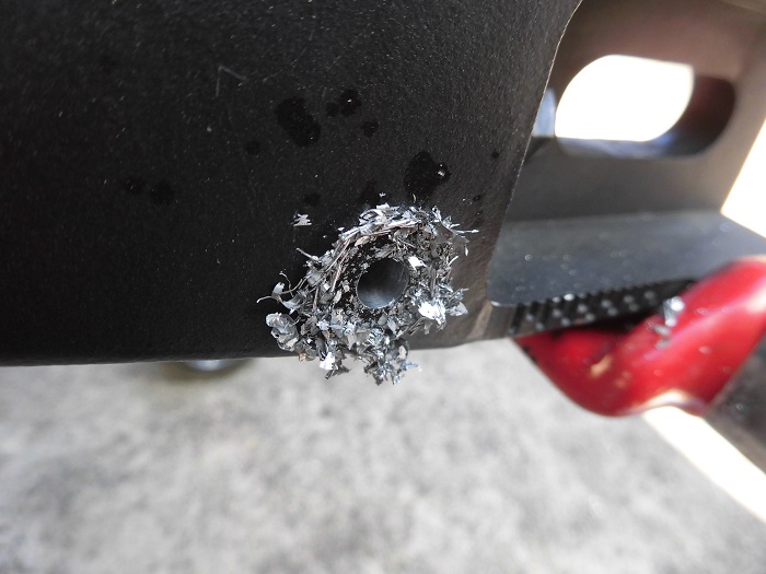
<With a hole drilled 2>
I made a hole like this.
A great success for me.
It did not core off significantly.
Chips left after cutting
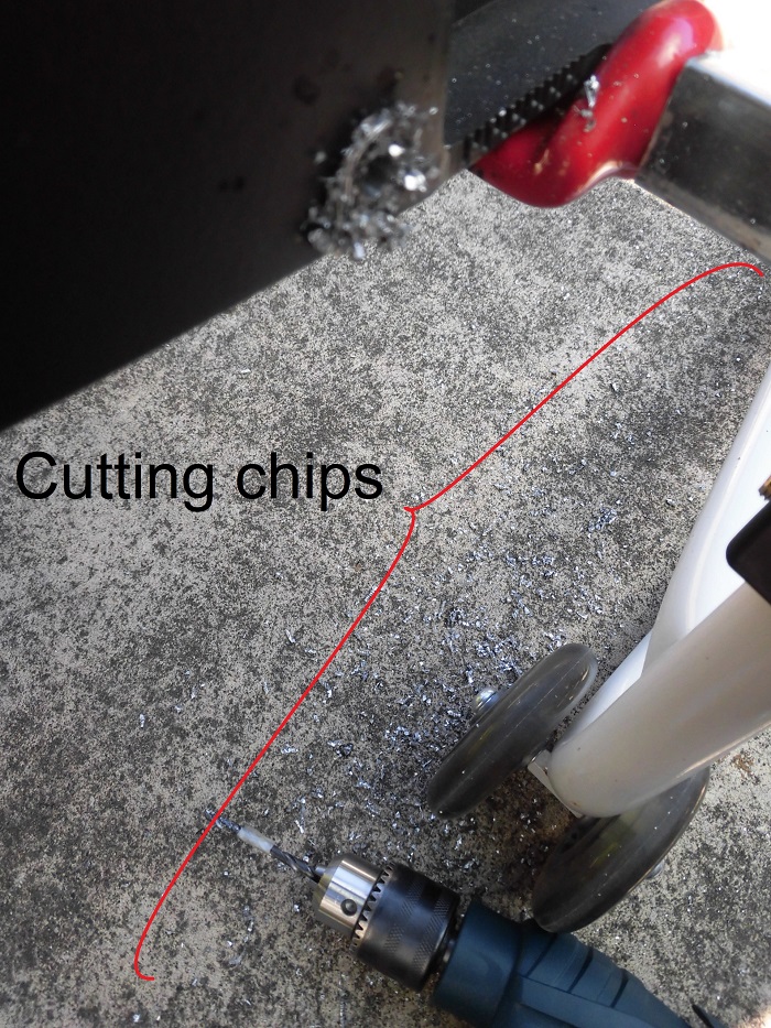
<Chips left after cutting>
The part that was cut was not hollow but a lump of aluminum, so it produced quite a lot of cutting chips.
The shavings splashed around the rear paddock stand and chain.
I should have covered it with a plastic sheet beforehand.
Chamfering of hole
<Chamfering of hole>
Chamfer the holes with a 13 mm drill.
An electric drill was not used, but lightly cut by hand.
Threading 1
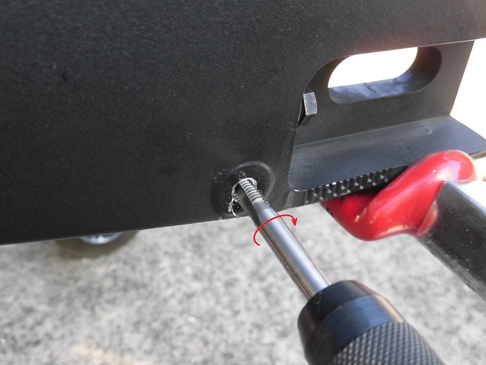
<Threading 1>
A tap (M6 pitch 1.0) with a handle was attached to the tap and threaded (screwed) into the hole.
The process was carried out slowly while applying cutting oil.
Cleaning threaded hole
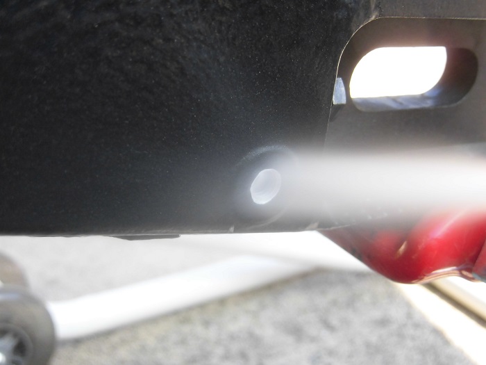
<Cleaning threaded hole>
Then, the screw hole was cleaned with parts cleaner and air blowers.
Threaded hole
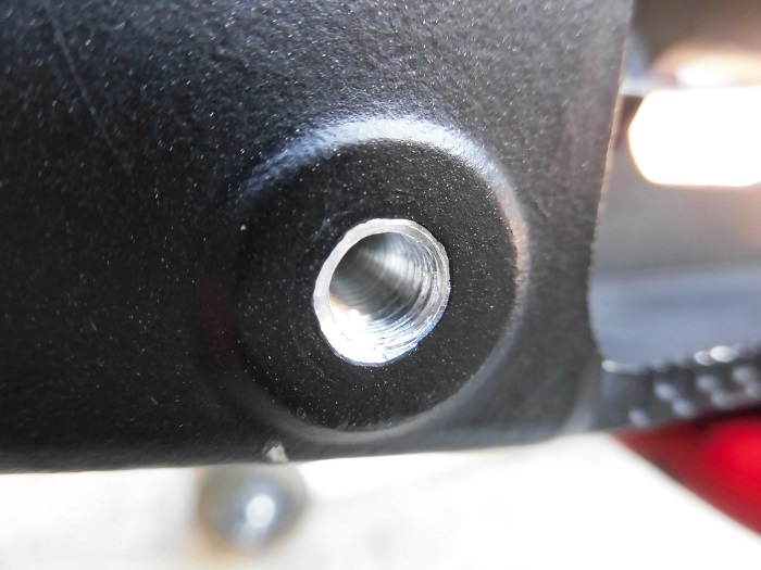
<Threaded hole>
I managed to process it successfully.
Scratches on muffler
Meanwhile, the right side proceeded in the same way, but the muffler made it difficult to work with…
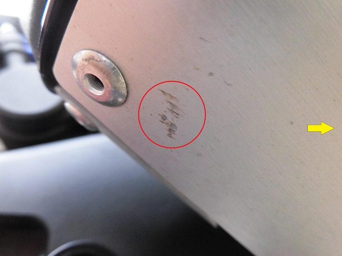
<Scratches on muffler>
When drilling the hole, the electric drill hit the muffler and scratched it somewhat.
Threading 2
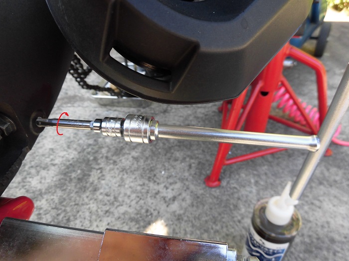
<Threading 2>
The handle hit the muffler when machining the screw.
So, I used a T-bar handle with a socket (5.5 mm) instead.
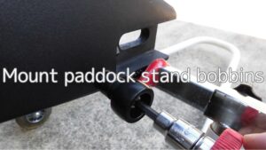
Mount bobbins
In the next issue, the bobbins will finally be installed.
(For details, see maintenance record “Mount paddock stand bobbins”).
3. Summary
The holes could be drilled in the seat without significant misalignment of the center.
Note that even if the machining of the screw holes failed,
Note that even if the machining of the threaded hole fails, it may still be possible to repair it by.
- Drilling a larger hole
- Inserting a recoil, etc.
- Using a guide bar keeps the hole from being significantly off-center.
- Cutting chips scatter unexpectedly.
- The right-hand side has a muffler, so the workspace is small.